Laser-Shaped Optical Fibers Along with Optical Assemblies and Methods Therefor

a technology of laser-shaped optical fibers and optical assemblies, which is applied in the direction of optical elements, manufacturing tools, instruments, etc., can solve the problems of increased attenuation, inability to meet the requirements of the splice section, so as to reduce or eliminate the glass defect zone and minimize the core gap in the mechanical splice section

Inactive Publication Date: 2010-12-02
CORNING OPTICAL COMM LLC
View PDF6 Cites 57 Cited by
  • Summary
  • Abstract
  • Description
  • Claims
  • Application Information

AI Technical Summary

Benefits of technology

[0007]Disclosed are optical assemblies such as field-installable connectors having a laser-shaped optical fiber along with methods for making the same. The present disclosure describes various methods for using a laser to cut and shape an end face of an optical fiber in general, and an optical fiber stub of a field-installable connector. The fiber laser processing methods described below substantially reduce or eliminate a glass defect zone, produce an edge radius that aids fiber insertion into a mechanical splice assembly while minimizing skiving, and produce a generally convex or domed angled fiber end face that minimizes the core gap in a mechanical splice section. The laser-shaped optical fiber can be used in any suitable optical assembly such as a mechanical splice device like a field installable connector.

Problems solved by technology

First, they have an inherent glass defect zone that is a result of the mechanical blade striking the glass fiber.
Second, they have sharp edges between the cleave face and the fiber outer diameter.
This angle may increase the fiber core gap when the fibers are butted in the mechanical splice assembly, which increases attenuation.
In addition to these disadvantages, mechanical cleavers require periodic cleaver blade replacement and are not automation friendly devices due to long-term instability.
In practice it is difficult task to perform an angled cleave in a repeatable and reproducible fashion.

Method used


Image

  • Laser-Shaped Optical Fibers Along with Optical Assemblies and Methods Therefor
  • Laser-Shaped Optical Fibers Along with Optical Assemblies and Methods Therefor
  • Laser-Shaped Optical Fibers Along with Optical Assemblies and Methods Therefor

Examples


Embodiment Construction

[0025]The concepts will now be described more fully hereinafter with reference to the accompanying drawings in which preferred embodiments are shown. This invention may, however, be embodied in many different forms and should not be construed as limited to the embodiments set forth herein. These exemplary embodiments are provided so that this disclosure will be both thorough and complete, and will fully convey the scope of the concepts to those skilled in the art. Like reference numbers refer to like elements throughout the various drawings.

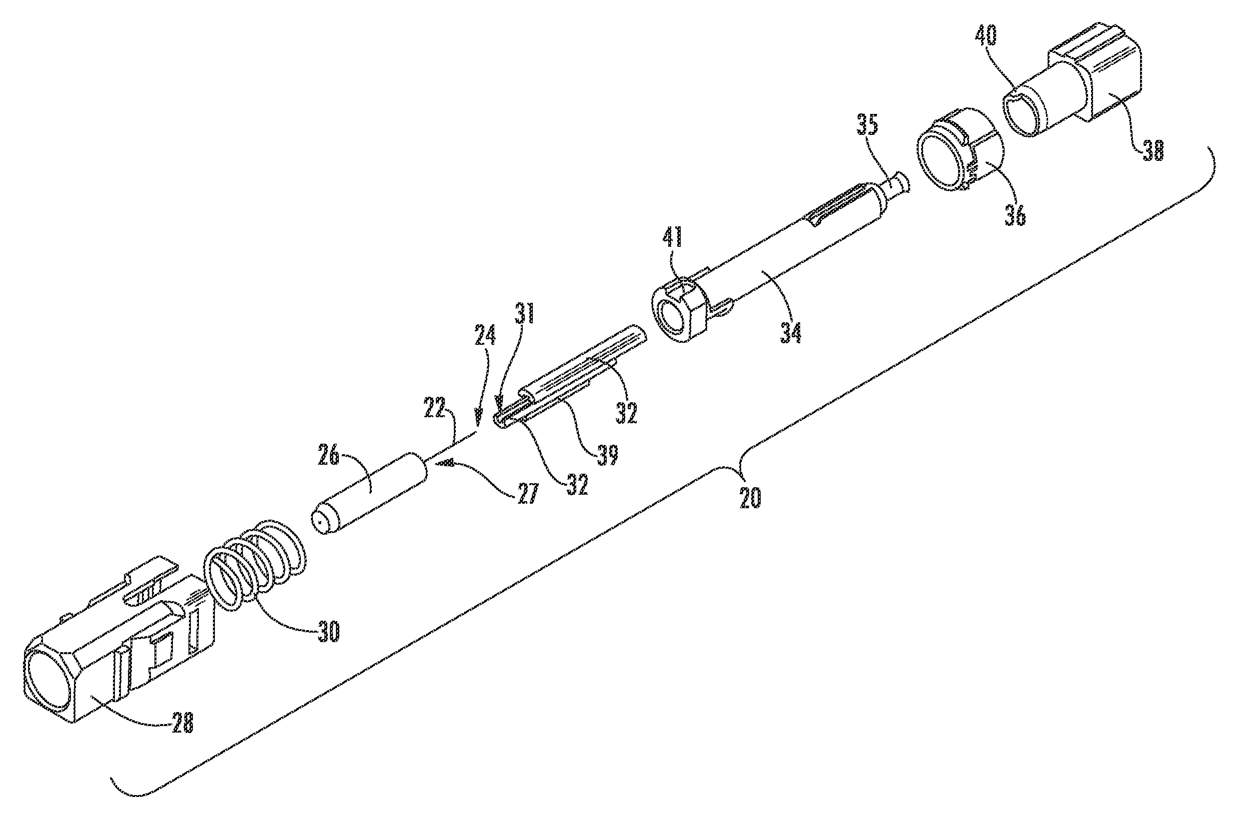
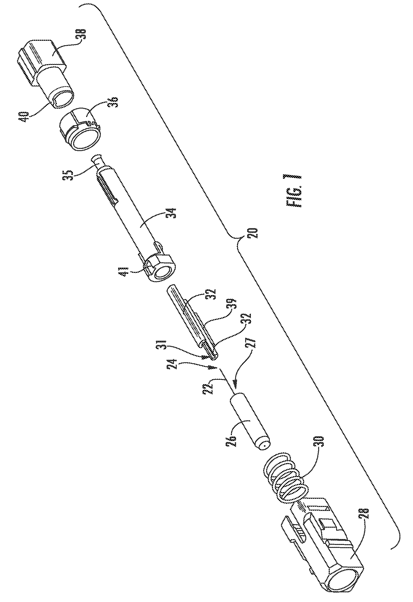
[0026]Referring now to the drawings, FIG. 1 shows an exemplary embodiment of a field-installable connector 20 (i.e., mechanical splice connector) having a stub optical fiber 22 with a laser-shaped tapered and angled end face 24. The laser-shaped stub optical fiber replaces a conventional mechanically cleaved fiber stub in a field-installable connector. During installation of connector 20, optical fibers may be brought into physical contact within...


PUM

PropertyMeasurementUnit
angleaaaaaaaaaa
angleaaaaaaaaaa
incident angleaaaaaaaaaa

Abstract

Disclosed are optical assemblies such as field-installable connectors having a laser-shaped optical fiber along with methods for laser-shaping the optical fiber. The field-installable connector includes a ferrule having front and rear opposed faces and at least one fiber bore defined longitudinally therethrough, a stub optical fiber having a distal end with a laser-shaped end face is disposed within the at least one fiber bore of the ferrule and extends a predetermined distance beyond the rear face of the ferrule, and an alignment feature operable for aligning the stub optical fiber with the field optical fiber. One method of laser-shaping the optical fiber includes rotating the optical fiber and sweeping a beam of a laser across the optical fiber and then essentially stopping the rotation of the optical fiber and sweeping the beam through the optical fiber to cut the same with a tapered and angled end face. Other methods may include shifting the laser relative to the optical fiber to create a “pencil-tip” end on the optical fiber.

Description

FIELD[0001]The present disclosure relates generally to laser-shaped optical fibers and optical assemblies such as field-installable connectors having a mechanical splice along with methods for laser-shaping optical fibers. In one embodiment, the disclosure is directed to a method for cutting and laser-shaping an optical fiber with a tapered and angled end face along with optical assemblies using the same.TECHNICAL BACKGROUND[0002]Optical fibers are used for a variety of applications including voice communication, data transmission and the like. With their ever increasing and varied use, it is apparent that efficient methods of splicing optical fibers are required. In order to efficiently couple the signals transmitted between respective optical fibers, the method of splicing the optical fibers must not significantly attenuate or alter the transmitted signals. Currently, there are two main methods for splicing optical fibers: fusion splicing and mechanical splicing. Mechanical splici...

Claims


Application Information

Patent Timeline
Patent Type & Authority Applications(United States)
IPC IPC(8): G02B6/38B23K26/38
CPCG02B6/25G02B6/3801B23K2103/50B23K26/40G02B6/3846
Inventor DANLEY, JEFFREY D.ROSSON, JOEL C.
Owner CORNING OPTICAL COMM LLC
Why Eureka
Try Eureka