Method of making an optical fiber by laser cleaving

a laser cleaving and optical fiber technology, applied in the field of connecting devices, can solve the problems of increasing attenuation, mechanical cleaving has an inherent glass defect zone, and mechanical cleavers typically produce sharp edges between the cleaved endface and the outer diameter of the fiber, so as to reduce or eliminate the glass defect zone and minimize the core gap of the mechanical splice

Active Publication Date: 2007-05-15
CORNING OPTICAL COMM LLC
View PDF16 Cites 77 Cited by
  • Summary
  • Abstract
  • Description
  • Claims
  • Application Information

AI Technical Summary

Benefits of technology

[0008]To achieve the foregoing and other objects, and in accordance with the purposes of the invention as embodied and broadly described herein, the present invention provides various embodiments of a field-installable connector including a stub optical fiber having an endface that is processed using a laser. The present invention also describes various embodiments of using a laser to cut and shape an endface of an optical fiber in general, and in particular to cut and shape a stub optical fiber of a field-installable connector. The laser processing methods described herein substantially reduce or eliminate a glass defect zone, produce an edge radius that aids fiber insertion into a mechanical splice assembly while minimizing skiving, and produce a generally convex (i.e., dome shaped), endface on a stub optical fiber that minimizes the core gap in a mechanical splice. A laser processed stub optical fiber according to the present invention may replace a mechanically cleaved stub optical fiber in a field-installable connector while solving at least some of the disadvantages described above.
[0009]In one exemplary embodiment, the present invention is a field-installable connector comprising a ferrule housing, a ferrule having front and rear opposed faces and at least one fiber bore extending longitudinally therethrough, a stub optical fiber having a laser processed endface disposed within the at least one fiber bore of the ferrule and extending a predetermined distance outwardly beyond the rear face, a ferrule holder, and an alignment feature operable for centering the end of the stub optical fiber and the end of a field optical fiber to produce a mechanical splice. The stub optical fiber and the field optical fiber are brought into end-to-end physical contact and secured in place within the field-installable connector using a securing means. The stub optical fiber having a laser processed endface replaces a mechanically cleaved stub optical fiber in a conventional field-installable connector for producing an improved quality mechanical splice.

Problems solved by technology

First, mechanical cleaves have an inherent glass defect zone that is a result of the mechanical blade striking the glass fiber.
Second, mechanical cleavers typically produce sharp edges between the cleaved endface and the outer diameter of the fiber.
Third, mechanical cleavers typically produce substantially flat fiber endfaces with cleave angles that may not be perpendicular to the longitudinal axis of the fiber.
The cleave angle may increase the core gap that results when two cleaved fibers are butted together in the mechanical splice assembly without regard for the orientation of their cleave angles, which increases attenuation.
In addition to these disadvantages, mechanical cleavers require periodic replacement of the cleaver blade and are not conducive to automation due to long-term instability.

Method used


Image

  • Method of making an optical fiber by laser cleaving
  • Method of making an optical fiber by laser cleaving
  • Method of making an optical fiber by laser cleaving

Examples


Embodiment Construction

[0022]The present invention will now be described more fully hereinafter with reference to the accompanying drawings in which exemplary embodiments of the invention are shown. However, this invention may be embodied in many different forms and should not be construed as limited to the embodiments set forth herein. These exemplary embodiments are provided so that this disclosure will be both thorough and complete, and will fully convey the scope of the invention to those skilled in the art. Like reference numbers refer to like elements throughout the various drawings.

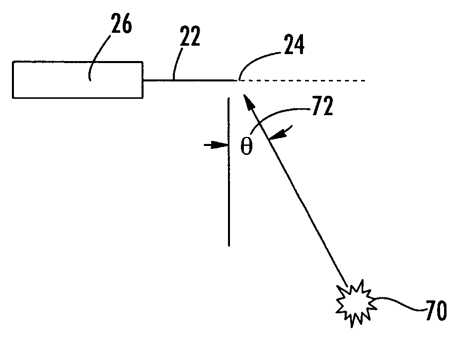
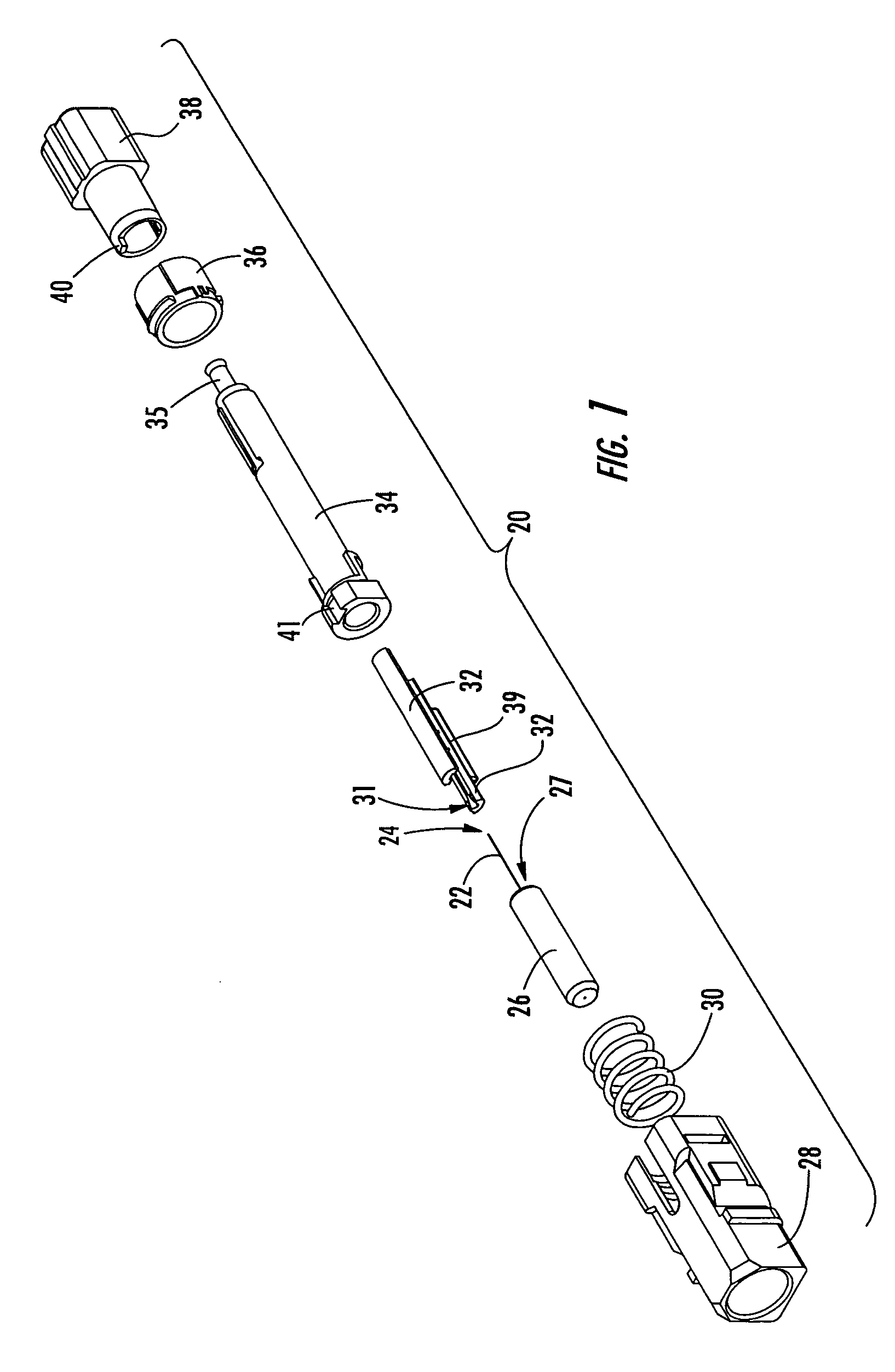
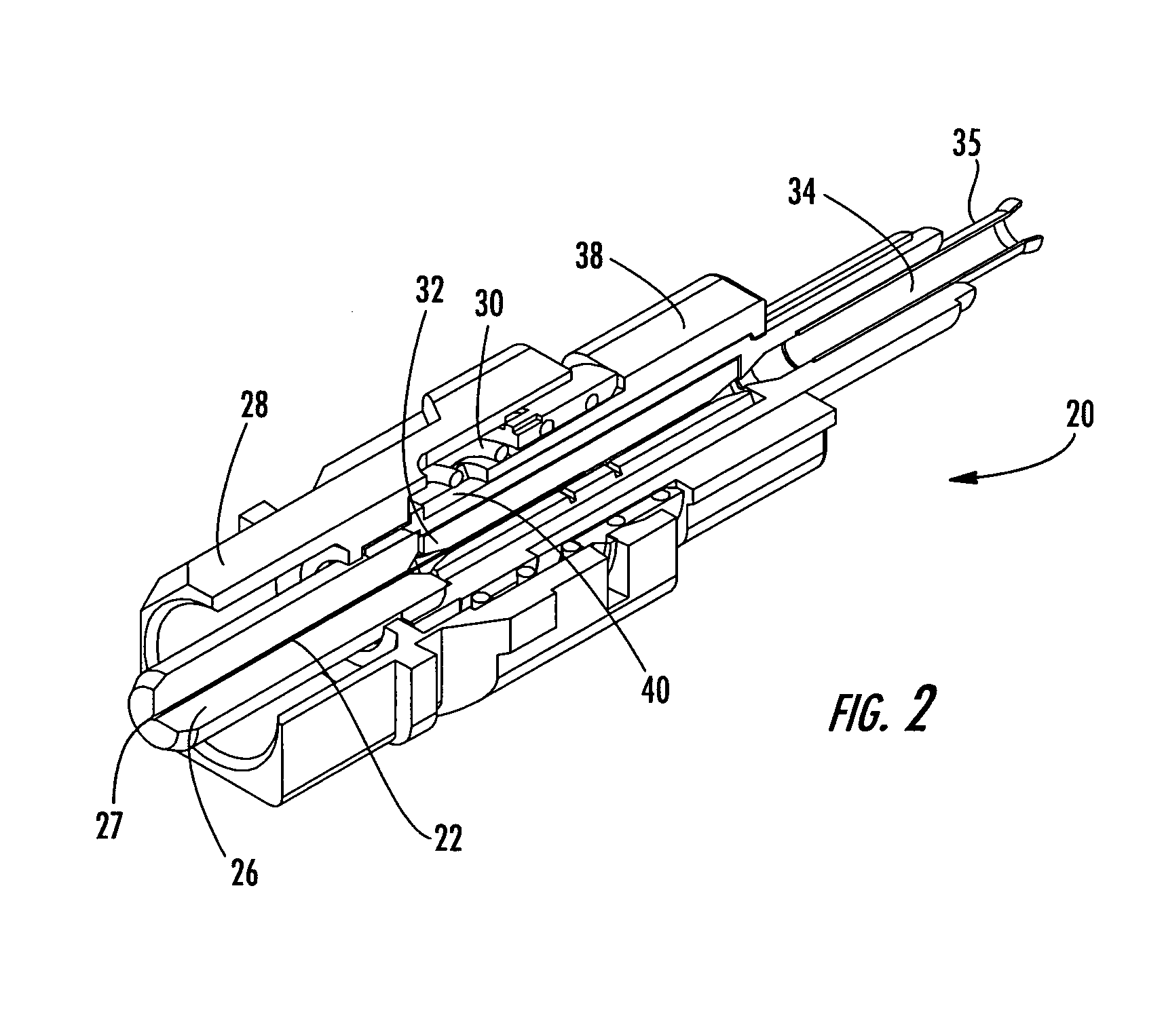
[0023]Referring now to the drawings, FIG. 1 shows an exemplary embodiment of a field-installable connector 20 including a stub optical fiber 22 processed using a laser. In particular, the stub optical fiber 22 is cut and the endface 24 of the stub optical fiber 22 is shaped using a laser, such as a focused-beam CO2 laser. The laser processed stub optical fiber 22 may replace a mechanically cleaved stub optical fiber in a...


PUM

PropertyMeasurementUnit
angleaaaaaaaaaa
angleaaaaaaaaaa
diameteraaaaaaaaaa

Abstract

A field-installable connector includes a connector housing and a ferrule having front and rear opposed faces and at least one fiber bore defined longitudinally therethrough. A laser processed stub optical fiber is disposed within the one fiber bore of the ferrule and extends a predetermined distance beyond the rear face of the ferrule. An alignment feature is operable for self-centering the stub optical fiber and a field optical fiber to perform a mechanical splice using a camming means. A method of laser processing a stub optical fiber includes rotating the stub optical fiber and sweeping a laser beam directed at a desired angle back and forth across a surface of the optical fiber. An oscillating motion of the laser is driven by an intermittent sinusoidal signal that results in two deposits of energy onto the stub optical fiber followed by a cooling period before subsequent deposits of energy occur.

Description

BACKGROUND OF THE INVENTION[0001]1. Field of the Invention[0002]The present invention relates generally to a connector used in optical fiber mechanical splicing and, more particularly, to a field-installable connector including a stub optical fiber having a laser shaped endface.[0003]2. Description of the Related Art[0004]Optical fibers are used for a variety of applications including voice communication, data transmission and the like. With the ever increasing and varied use of optical fibers, it is apparent that more efficient methods of splicing optical fibers are required. In order to effectively couple the signals transmitted between respective optical fibers, the method of splicing the optical fibers must not significantly attenuate, reduce or alter the transmitted signals. Currently, there are two common methods for splicing optical fibers: fusion splicing and mechanical splicing. Mechanical splicing, the method employed in the present invention, is a process for mating the e...

Claims


Application Information

Patent Timeline
Patent Type & Authority Patents(United States)
IPC IPC(8): C03B37/16G02B6/36B23K26/08B23K26/10B23K26/16G02B6/25G02B6/255G02B6/38
CPCB23K26/0823B23K26/16G02B6/2552G02B6/3846G02B6/3806G02B6/38875
Inventor DANLEY, JEFF D.WACASTER, T. BRIANROSSON, JOEL C.
Owner CORNING OPTICAL COMM LLC
Why Eureka
Try Eureka