Rainwater catchment apparatus and plant cultivating system having rainwater catchment apparatus
Inactive Publication Date: 2010-12-09
SUNTORY HLDG LTD
View PDF2 Cites 12 Cited by
Summary
Abstract
Description
Claims
Application Information
AI Technical Summary
This helps you quickly interpret patents by identifying the three key elements:
Problems solved by technology
Method used
Benefits of technology
Benefits of technology
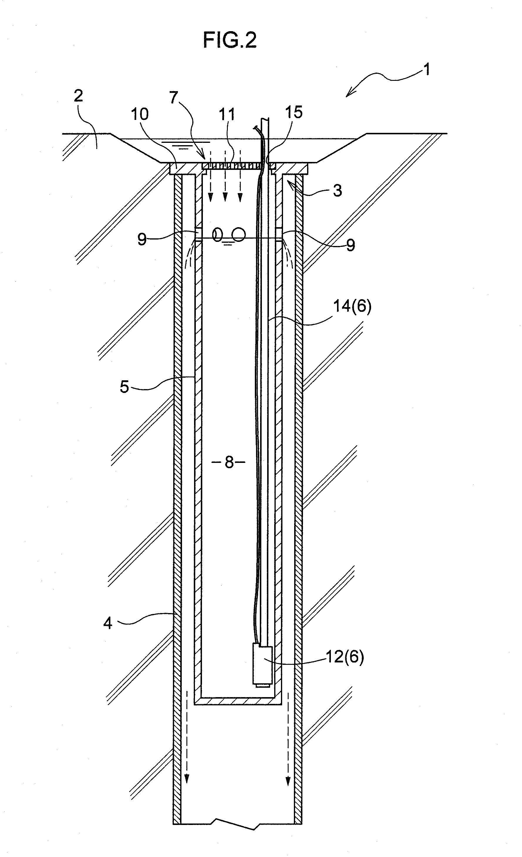
[0014]The rainwater catchment apparatus of the present invention can be easily mounted on the existing rainwater outlet of the building without renovating the building.
[0015]More particularly, in installing the rainwater catchment apparatus of the present invention, it is only required that the reservoir be fitted into the rainwater outlet to engage the flange portion with the peripheral portion of the rainwater outlet.
[0016]Rainwater flowing into the rainwater outlet flows over the flange portion into the rainwater inlet and is stored in the reservoir. The stored rainwater is pumped by the pumping mechanism of the present invention to be used in various ways (watering on a plant or flushing in a toilet, for example).
[0017]According to the present invention, even if a large amount of water flows into the rese
Problems solved by technology
On the other hand, when the above-noted rainwater catchment apparatus is mounted on a new-built building, it is required to design the building to adapt the rainwater catchment apparatus to the building, which disadvantageously affects the efficiency in construction of the building.
Method used
Image
Click on the blue label to locate the original text in one second.
Reading with bidirectional positioning of images and text.
Examples
embodiments
[0079]Embodiments of a rainwater catchment apparatus 1 of the present invention will be described hereinafter.
[0080]Water collected by the rainwater catchment apparatus 1 of the present invention may be used in plant cultivation, for example, (that is to say, used in watering). A combination of the rainwater catchment apparatus 1 of the present invention and an appropriate plant cultivating apparatus easily forms a plant cultivating system which may simplify a watering operation to cultivate a plant effectively.
first embodiment
[0081]FIG. 5 schematically shows a plant cultivating system 18 comprising a rainwater catchment apparatus 1 of the present invention in combination with a plant cultivating apparatus.
[0082]The plant cultivating system 18 comprises the rainwater catchment apparatus 1, the plant cultivating apparatus for cultivating the plant, and a water-supply mechanism 17 for supplying water pumped by the rainwater catchment apparatus 1 to the plant cultivating apparatus.
[0083]In the plant cultivating system 18, water stored in the water-storage tank 13 of the rainwater catchment apparatus 1 is automatically supplied to the plant cultivating apparatus through the water-supply mechanism 17.
[0084]In particular, when the plant cultivating system 18 is used in a rooftop of a building, for example, it is possible to arrange the rainwater catchment apparatus 1 and the plant cultivating apparatus in proximity to each other, which can save working energy in the pumping mechanism 6 or the water-supply mecha...
second embodiment
[0121]FIG. 17 schematically shows another plant cultivating system 18 different from that of the first embodiment described above. The plant cultivating system 18 comprises the rainwater catchment apparatus 1, the plant cultivating apparatus 16b for cultivating the plant, and the water-supply mechanism 17 for supplying water pumped up by the rainwater catchment apparatus 1 to the plant cultivating apparatus 16b.
[0122]In the plant cultivating system 18, water stored in the water-storage tank 13 of the rainwater catchment apparatus 1 is automatically supplied to the plant cultivating apparatus 16b by the water-supply mechanism 17.
[0123]In particular, when the plant cultivating system 18 is used in the rooftop of the building, for example, it is possible to arrange the rainwater catchment apparatus 1 and the plant cultivating apparatus in proximity to each other, which can save working energy in the pumping mechanism 6 or the water-supply mechanism 17 of the rainwater catchment appara...
PUM
Abstract
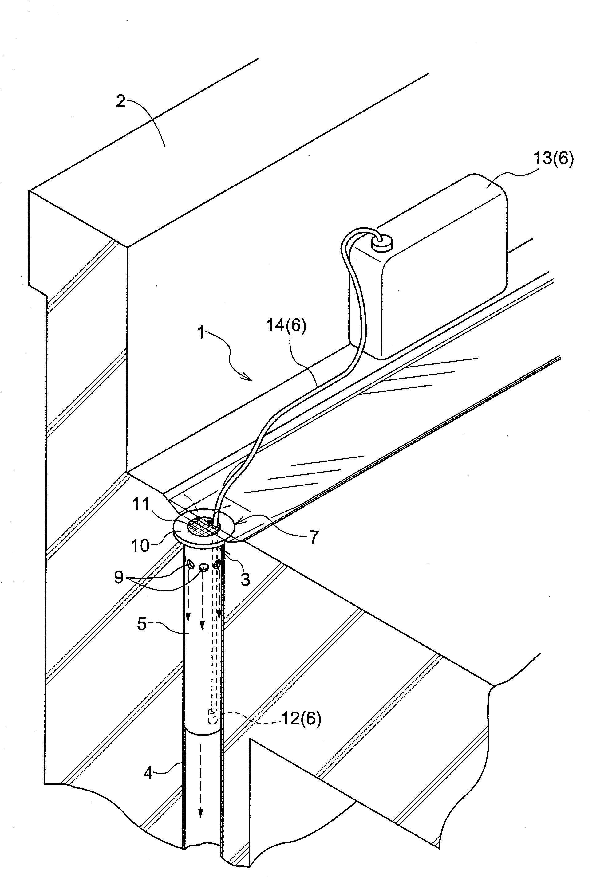
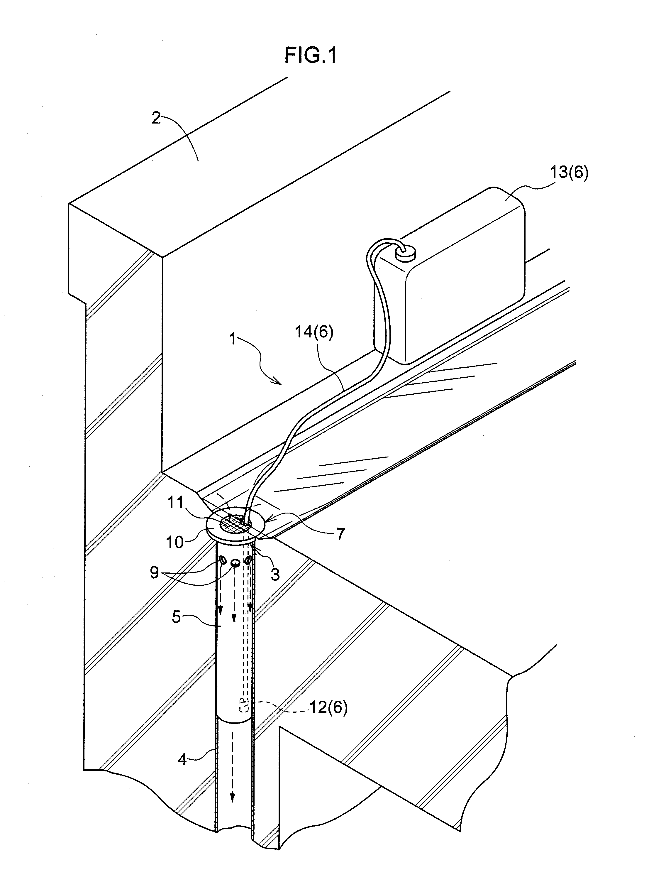
The present invention provides a rainwater catchment apparatus that is easily installed without renovating a building. The rainwater catchment apparatus comprises a rainwater inlet for introducing rainwater, a flange portion engaged with a peripheral portion of a rainwater outlet serving as a leading end of a drainage canal formed in a building framework for introducing rainwater in the rainwater inlet, a drain portion for discharging excessive water exceeding a predetermined level to the drainage canal, a reservoir freely fitted into the drainage canal through the rainwater outlet, and a pumping mechanism for pumping water stored in the reservoir to the outside.
Description
TECHNICAL FILED[0001]The present invention relates to a rainwater catchment apparatus comprising a reservoir for storing rainwater flowing into a rainwater outlet formed in a building framework, and a pumping mechanism for pumping water stored in the reservoir.BACKGROUND ART[0002]The above-noted rainwater catchment apparatus is adapted to efficiently collect rainwater falling on a roof or rooftop of the building framework (a residential house or building, for example). Rainwater collected can be used in various ways (for watering on a plant or flushing in a toilet, for example).[0003]As the conventional art relating to such a rainwater catchment apparatus, Patent Document 1 has proposed water catchment equipment having the reservoir for collecting rainwater that is provided in the front of the house or building, for example.[0004][Patent Document 1] Japanese Patent Publication No. 56-38733DISCLOSURE OF THE INVENTION[0005]When the conventional rainwater catchment apparatus noted abov...
Claims
Application Information
Patent Timeline
Application Date:The date an application was filed.
Publication Date:The date a patent or application was officially published.
First Publication Date:The earliest publication date of a patent with the same application number.
Issue Date:Publication date of the patent grant document.
PCT Entry Date:The Entry date of PCT National Phase.
Estimated Expiry Date:The statutory expiry date of a patent right according to the Patent Law, and it is the longest term of protection that the patent right can achieve without the termination of the patent right due to other reasons(Term extension factor has been taken into account ).
Invalid Date:Actual expiry date is based on effective date or publication date of legal transaction data of invalid patent.

