Cutting elements including cutting tables with shaped faces configured to provide continuous effective positive back rake angles, drill bits so equipped and methods of drilling

a technology of cutting elements and drill bits, which is applied in the direction of drilling machines, methods, rotary drilling, etc., can solve the problems of increasing the difficulty of rotating the bit, increasing the difficulty of cutting the cutting point, and the likelihood of cutting the cutting element to fracture, etc., to reduce or eliminate the damage to the cutting point

Active Publication Date: 2010-12-09
BAKER HUGHES INC
View PDF45 Cites 47 Cited by
  • Summary
  • Abstract
  • Description
  • Claims
  • Application Information

AI Technical Summary

Benefits of technology

[0005]In one embodiment, the present invention includes cutting elements for drag-type earth-boring drill bits. A cutting element of the present invention includes a cutting table with a face that includes a cutting region configured to be oriented at a more aggressive rake angle than would otherwise be dictated by the configuration of a substrate of the cutting element, or by an orientation of the substrate relative to a blade of a drill bit. Due to an orientation of a cutting point along an edge of the face of the cutting table, the cutting point is in compression during drill...

Problems solved by technology

While the orientation of cutting elements at negative back rake angles has long been used and has proven to be an effective technique for drilling bore holes, there are a number of undesirable effects when conventionally configured cutting elements with cutting tables that include planar faces are used.
The continuous presence of cuttings against the cutting face of the PDC cutting table of a cutting element may inhibit cooling of the PDC cutting table, which may cause an undesirably high likelihood that the cutting elements will fracture, break off of the cutting elements, or otherwise fail.
In addition, the collecti...

Method used


Image

  • Cutting elements including cutting tables with shaped faces configured to provide continuous effective positive back rake angles, drill bits so equipped and methods of drilling
  • Cutting elements including cutting tables with shaped faces configured to provide continuous effective positive back rake angles, drill bits so equipped and methods of drilling
  • Cutting elements including cutting tables with shaped faces configured to provide continuous effective positive back rake angles, drill bits so equipped and methods of drilling

Examples


Embodiment Construction

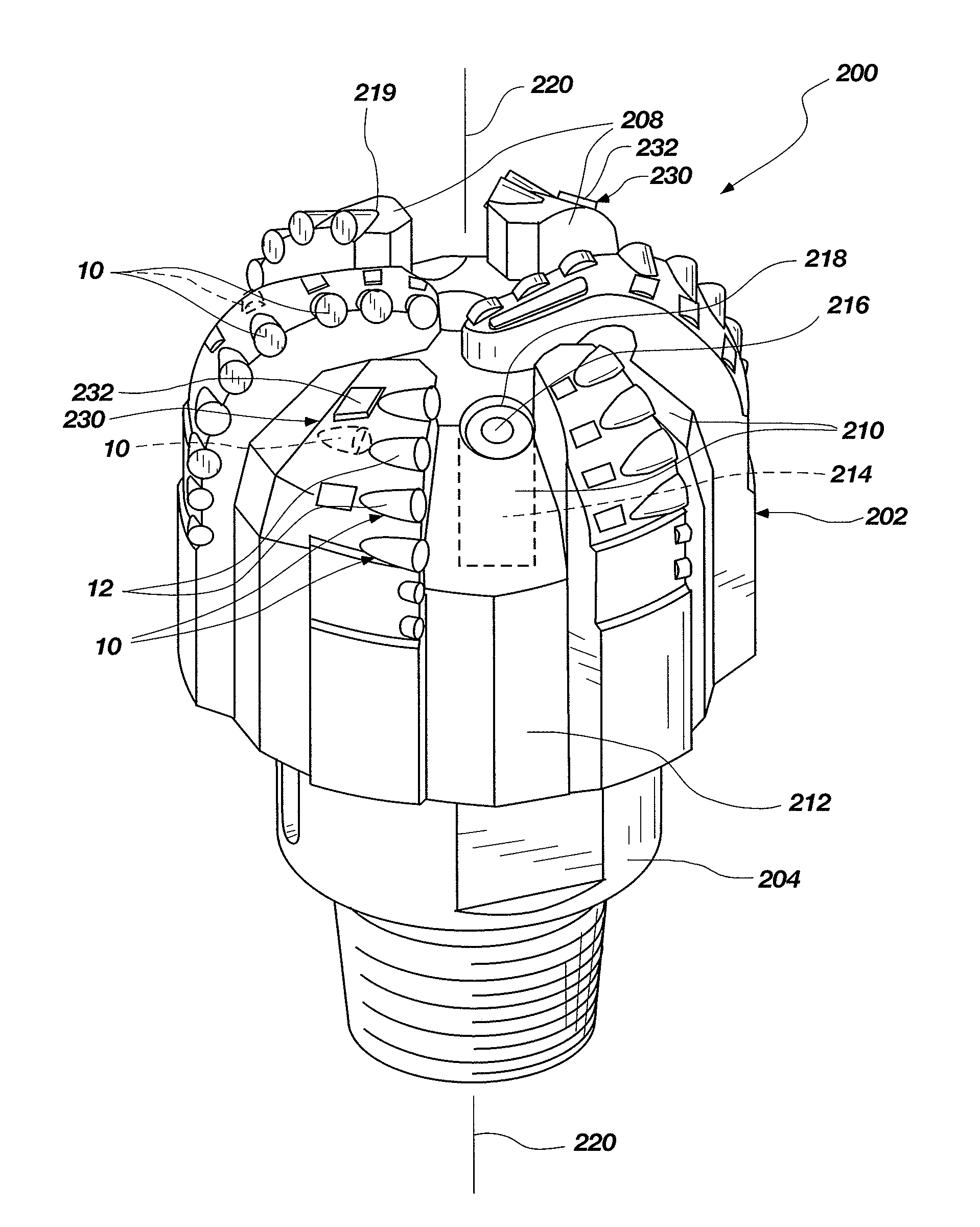
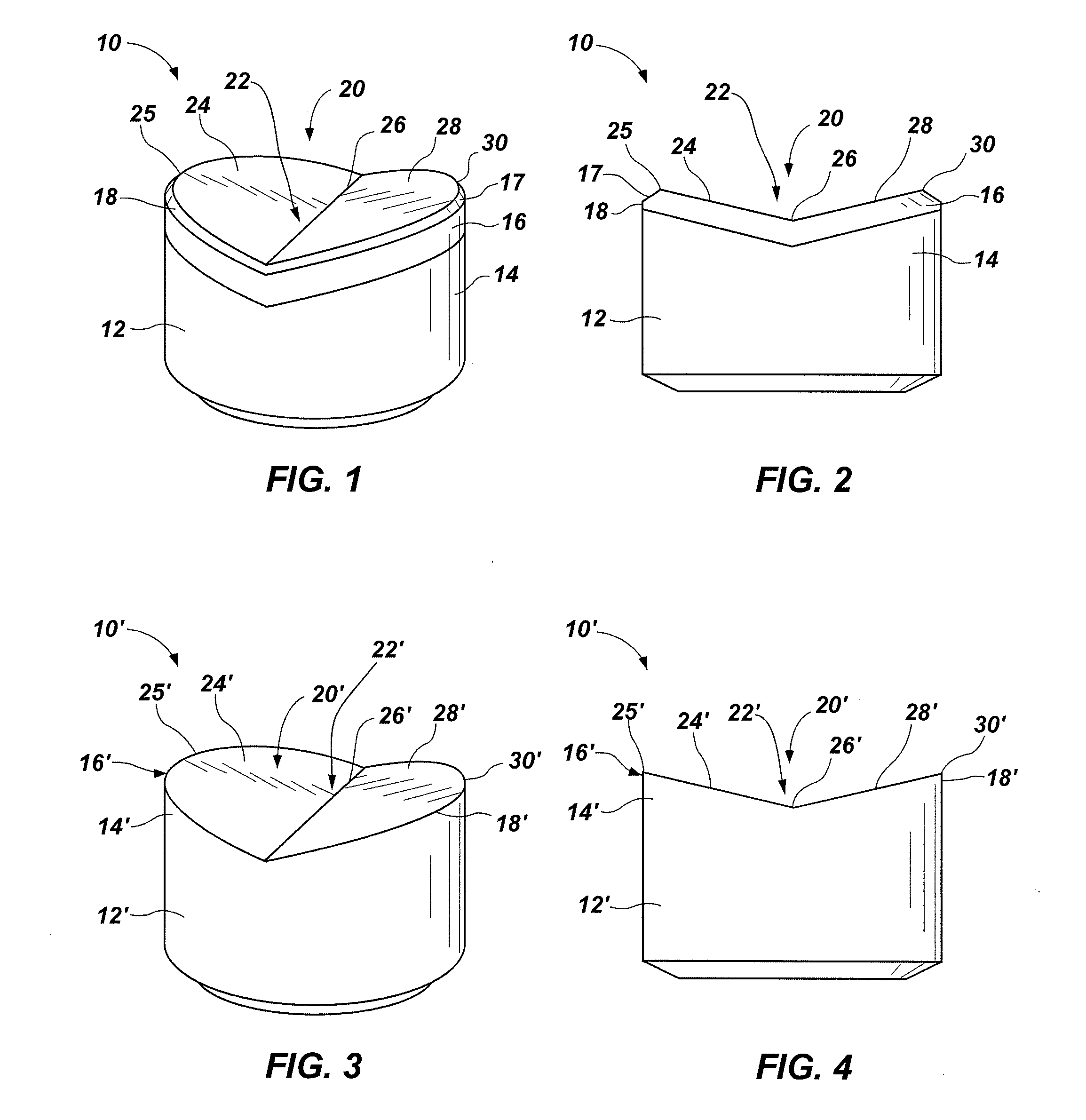
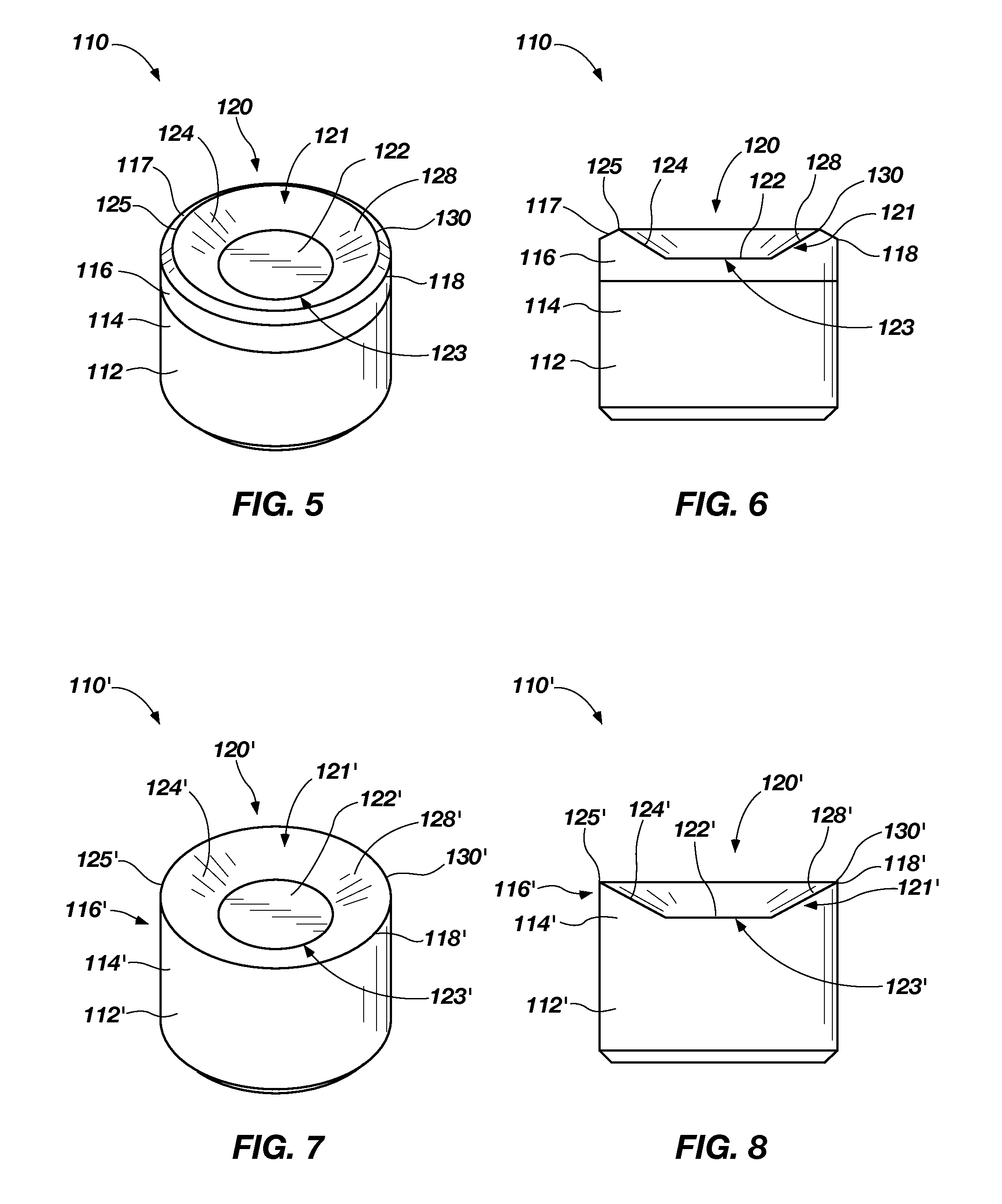
[0017]FIGS. 1 through 4 illustrate embodiments of cutting elements 10, 10′ according to the present invention. Each cutting element 10, 10′ includes a substrate 12, 12′ and a cutting table 16, 16′ at an end 14, 14′ of substrate 12, 12′.

[0018]As depicted in FIGS. 1 and 2, some embodiments of a cutting element 10 include a cutting table 16 that has been secured to end 14 of substrate 12. [In such embodiments, cutting table 16 may comprise superabrasive material, as in a polycrystalline diamond compact (PDC), or a softer but still superabrasive material, such as cubic boron nitride (CBN) or a thermally stable polycrystalline diamond (TSP).

[0019]Another embodiment of cutting element 10′ according to the present invention is shown in FIGS. 3 and 4. A cutting table 16′ of cutting element 10′ is formed from an end 14′ of substrate 12′, rather than being secured to end 14′. In such an embodiment, cutting table 16′ may have the same or substantially the same composition as substrate 12′. Alt...


PUM


Abstract

A cutting element for a drag-type earth-boring drill bit includes a cutting table with a face including a region that is configured cut into a formation at an effective positive back rake angle and to direct formation cuttings, or chips, that have been cut from the earth formation toward the hydraulics of the drill bit. Drill bits that include one or more cutting elements that have been configured in this manner are also disclosed. Such a drill bit may also include a wear pad for limiting the depth to which a cutting element penetrates a surface of a bore hole in an earth formation. Such a wear pad may have a substantially constant thickness. Methods for removing material from earth formations are also disclosed.

Description

TECHNICAL FIELD[0001]The present invention, in various embodiments, relates generally to cutting elements for drag-type earth-boring drill bits and, more specifically, to cutting elements that are configured cut into a subterranean formation at an effective positive back rake angle and to direct formation cuttings, or chips, that have been cut from the earth formation toward the hydraulic flows of the drill bit. The present invention also relates to drill bits including such cutting elements, as well as to methods for drilling into a formation.RELATED ART[0002]Drag-type earth-boring drill bits typically carry a number of fixed cutting elements, or cutters, each comprising a polycrystalline diamond compact (PDC) cutting table carried on a supporting substrate, conventionally of cemented tungsten carbide. As such a drill bit is rotated and driven into and through an earth formation, the cutting elements follow a helical path, along which they cut into and remove material from the eart...

Claims


Application Information

Patent Timeline
IPC IPC(8): E21B10/55E21B10/42E21B10/567E21B7/00E21B3/00
CPCE21B2010/566E21B10/5673E21B10/5671
Inventor PATEL, SURESH G.
Owner BAKER HUGHES INC
Why Eureka
Try Eureka