Friction reducing downhole assemblies

a technology of friction reduction and assembly, which is applied in the direction of drilling casings, drilling rods, drilling pipes, etc., can solve the problems of reducing the service life of the assembly, the inability of the centralizer of the conventional roller sub to adjust to various conditions, and the inability to support the full weight of the tubing, casing or other pipe strings, etc., so as to reduce the friction and drag of sliding, reduce the friction and drag of rotation, and reduce the effect of pipe wear and fatigu

Active Publication Date: 2016-07-26
PREMIUM TOOLS LLC
View PDF14 Cites 5 Cited by
  • Summary
  • Abstract
  • Description
  • Claims
  • Application Information

AI Technical Summary

Benefits of technology

[0017]When utilized in oil and / or gas wells, the friction reducing assemblies of the present invention provide a number of significant operational benefits. Specifically, the friction reducing assemblies of the present invention allow pipe deployment in highly-deviated and / or horizontal wellbores. Said friction reducing assemblies substantially reduce rotational friction and torque in horizontal and diagonal planes, while reducing sliding friction and drag in vertical and diagonal planes. Further, although conventional roller subs typically only permit rotation about a longitudinal axis, the friction reducing assemblies of the present invention permit full 360-degree rotational contact between friction reducing elements and surrounding well or other surfaces.
[0018]Additionally, the friction reducing assemblies of the present invention reduce pipe wear and fatigue during deployment (and retrieval, if necessary), while also reducing or eliminating damage to liner tops and liners. Said assemblies permit deployment of tools conveyed via wireline and / or continuous tubing in highly deviated and horizontal wells, while reducing the risk of damage to exposed packer slips and seals.

Problems solved by technology

However, such conventional roller subs are typically not adjustable to various conditions within a well such as, for example, wells having multiple internal diameters.
However, such bow spring centralizers are typically not sturdy enough to support the full weight of tubing, casing or other pipe strings.
Additionally, such conventional centralizer roller subs typically include axles, grub screws and / or other mechanical components that are especially vulnerable to failure during use.

Method used


Image

  • Friction reducing downhole assemblies
  • Friction reducing downhole assemblies
  • Friction reducing downhole assemblies

Examples


Embodiment Construction

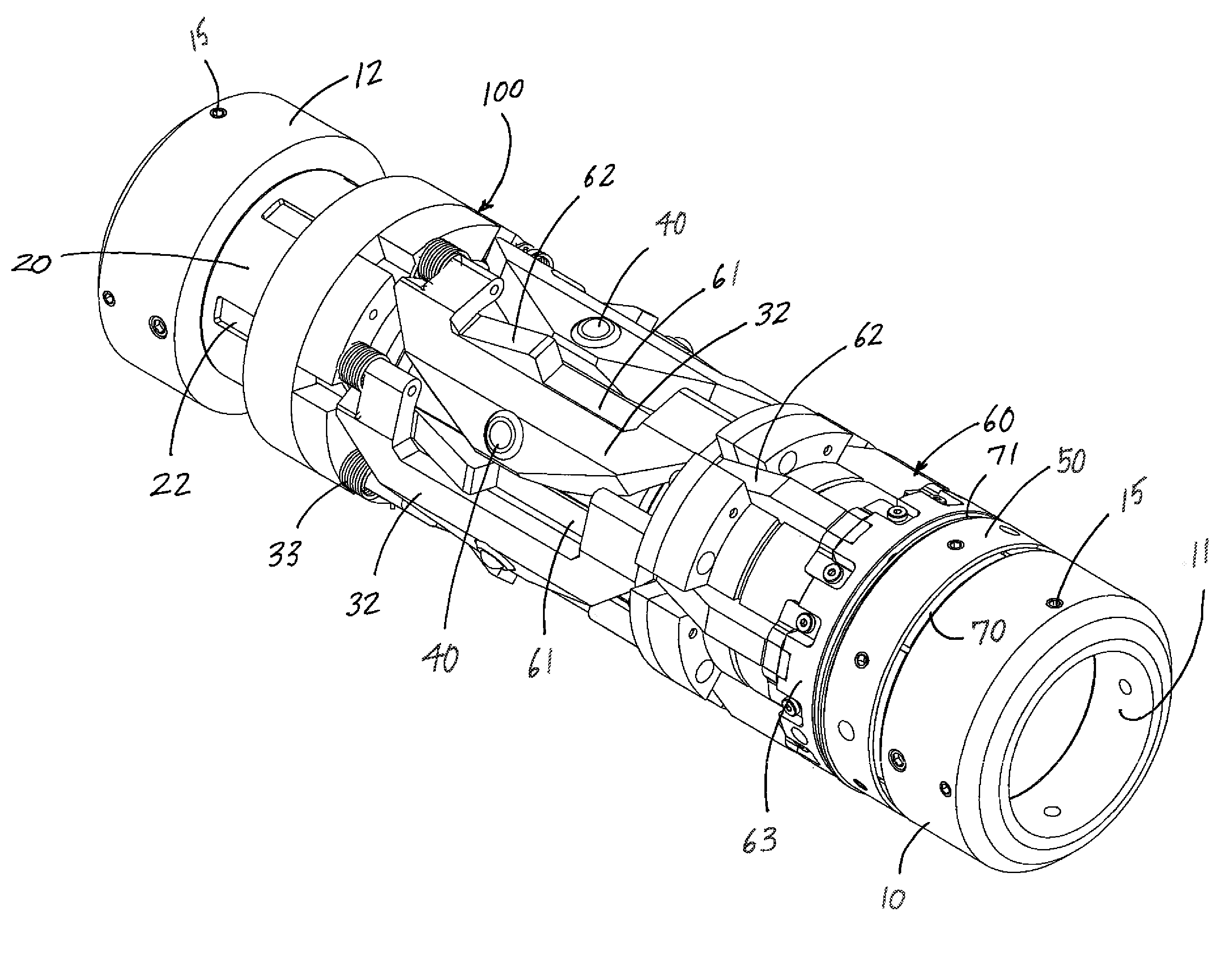
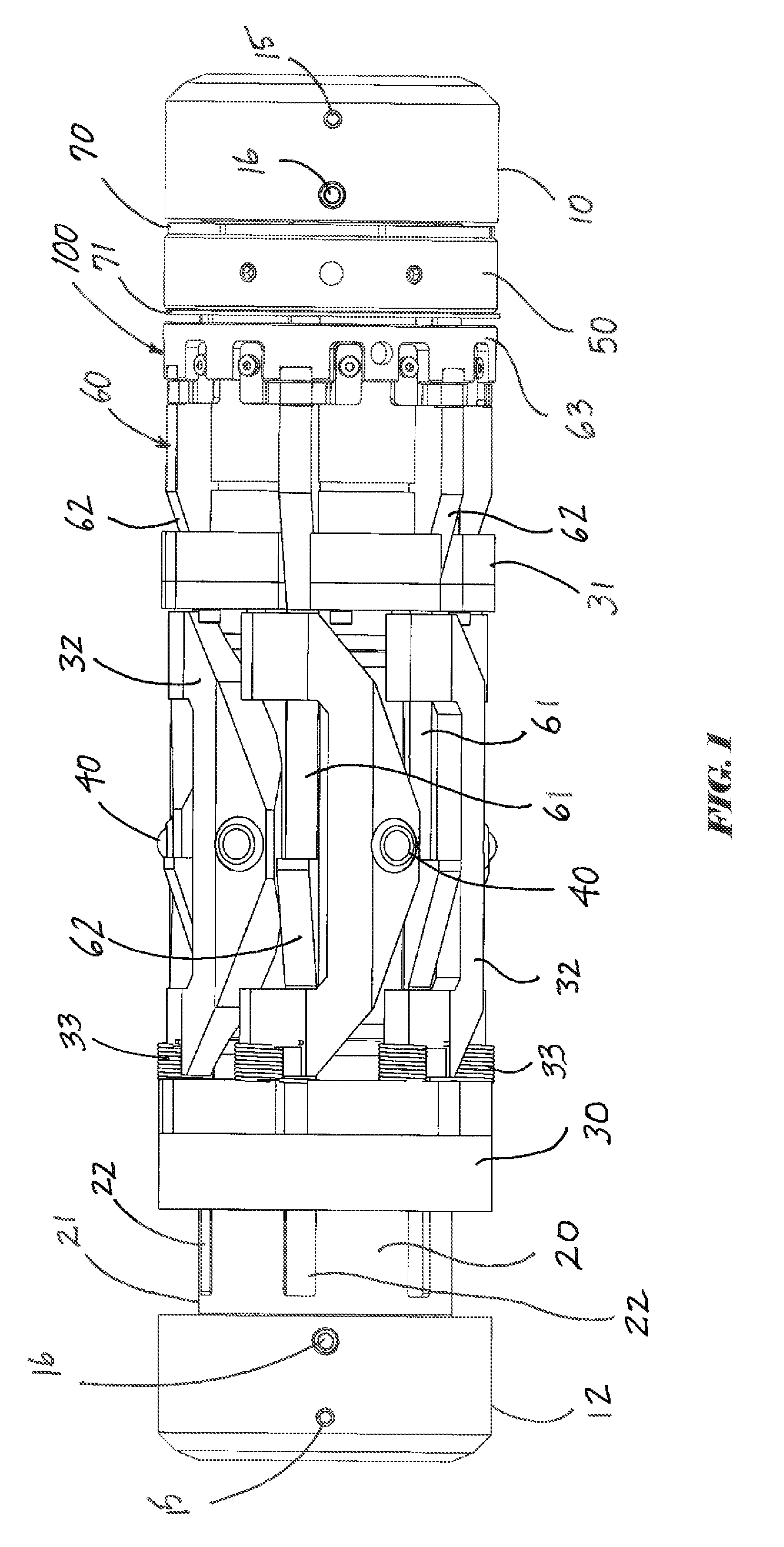
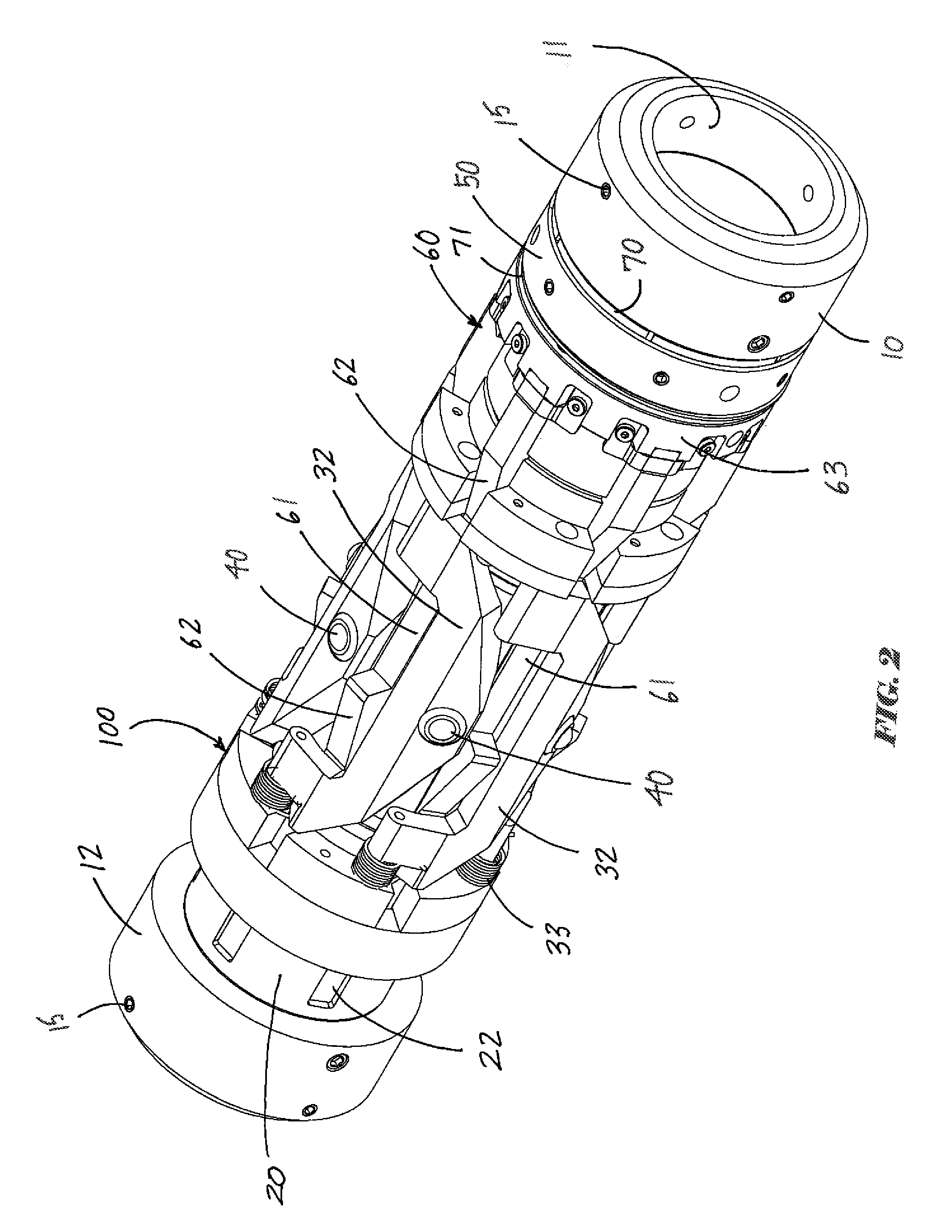
[0029]The present invention comprises an adjustable tension centralizer assembly 100 having a plurality of omni-directional rolling-element bearings that assist the delivery of a centralized tool, pipe section, tubular good, tool, or other device. More particularly, adjustable tension centralizer assembly 100 comprises an adjustable device having friction reducing rolling elements disposed in radially extendable arms. Said friction reducing elements contact and reduce frictional forces against the inner surface of a surrounding casing, hole, pipe or other surrounding enclosure. The adjustable centralizer assembly 100 of the present invention can be included within a larger pipe assembly using threaded connections, set screws, or other connection means well known to those having skill in the art.

[0030]Referring to the drawings, FIG. 1 depicts a side view of an adjustable tension centralizer assembly 100 of the present invention. In a preferred embodiment, said adjustable tension cent...


PUM


Abstract

A friction reducing assembly has a substantially cylindrical body member having an outer surface and friction reducing elements, such as ball transfer units or other omni-directional rolling-element bearing assemblies, disposed along such outer surface. The friction reducing assembly can take many different configurations including a rolling sub assembly, a mule shoe assembly or a centralizer assembly having an adjustable outer diameter.

Description

CROSS REFERENCES TO RELATED APPLICATION[0001]Priority of U.S. Provisional Patent application Ser. No. 61 / 781,167, filed Mar. 14, 2013, incorporated herein by reference, is hereby claimed.STATEMENTS AS TO THE RIGHTS TO THE INVENTION MADE UNDER FEDERALLY SPONSORED RESEARCH AND DEVELOPMENT[0002]NoneBACKGROUND OF THE INVENTION[0003]1. Field of the Invention[0004]The present invention pertains to downhole assemblies having friction reducing elements. More particularly, the present invention pertains to dowhole assemblies having at least one friction reducing element on at least one exterior surface to reduce frictional forces acting on said assemblies. More particularly still, the present invention pertains to downhole assemblies having at least one ball transfer unit on at least one exterior surface.[0005]2. Brief Description of the Prior Art[0006]During operations in the oil and gas industry, a pipe or substantially tubular tool having a certain outer diameter is frequently inserted or...

Claims


Application Information

Patent Timeline
Patent Type & Authority Patents(United States)
IPC IPC(8): E21B17/10
CPCE21B17/1014E21B17/1057
Inventor PERRY, KENNETH
Owner PREMIUM TOOLS LLC
Why Eureka
Try Eureka