Stop wall structure for removably mounting to a metal-wire shelf

a technology of stop structure and metal wire shelf, which is applied in the field of stop structure, can solve the problems of increasing the manufacturing cost and overall weight of metal, reducing the competitive ability of metal racks in the market, and affecting the appearance of the produ

Inactive Publication Date: 2010-12-09
PROTREND ENTERPRISE CO LTD
View PDF10 Cites 17 Cited by
  • Summary
  • Abstract
  • Description
  • Claims
  • Application Information

AI Technical Summary

Benefits of technology

[0006]A primary object of the present invention is to provide a stop wall structure for mounting to a front and two lateral edges of a metal-wire shelf for a sectional rack, for example, so that articles positioned on the metal-wire shelf are protected against falling therefrom.
[0007]Another object of the present invention is to provide a stop wall structure for removably mounting to a metal-wire shelf, so that the stop wall structure does not increase the packing, warehousing and transporting costs of a sectional rack using the metal-wire shelf.

Problems solved by technology

The metal-wire shelf 10 has four completely open sides, and articles positioned thereon are subject to undesirable falling therefrom.
If metal wires and metal bars are used to directly form upright stop walls (not shown) at four sides of the metal-wire shelf 10, these stop walls would inevitably increase the manufacturing cost and the overall weight of the metal-wire shelf to thereby reduce the competing ability of the metal rack in the market.
Further, the metal-wire shelf 10 with the upright stop walls formed with the metal wires and bars thereof tends to have a large volume that causes difficulty in packing the metal-wire shelf and increases the warehousing and transporting costs thereof to further reduce the competing ability of the sectional rack using such metal-wire shelf.

Method used


Image

  • Stop wall structure for removably mounting to a metal-wire shelf
  • Stop wall structure for removably mounting to a metal-wire shelf
  • Stop wall structure for removably mounting to a metal-wire shelf

Examples


Embodiment Construction

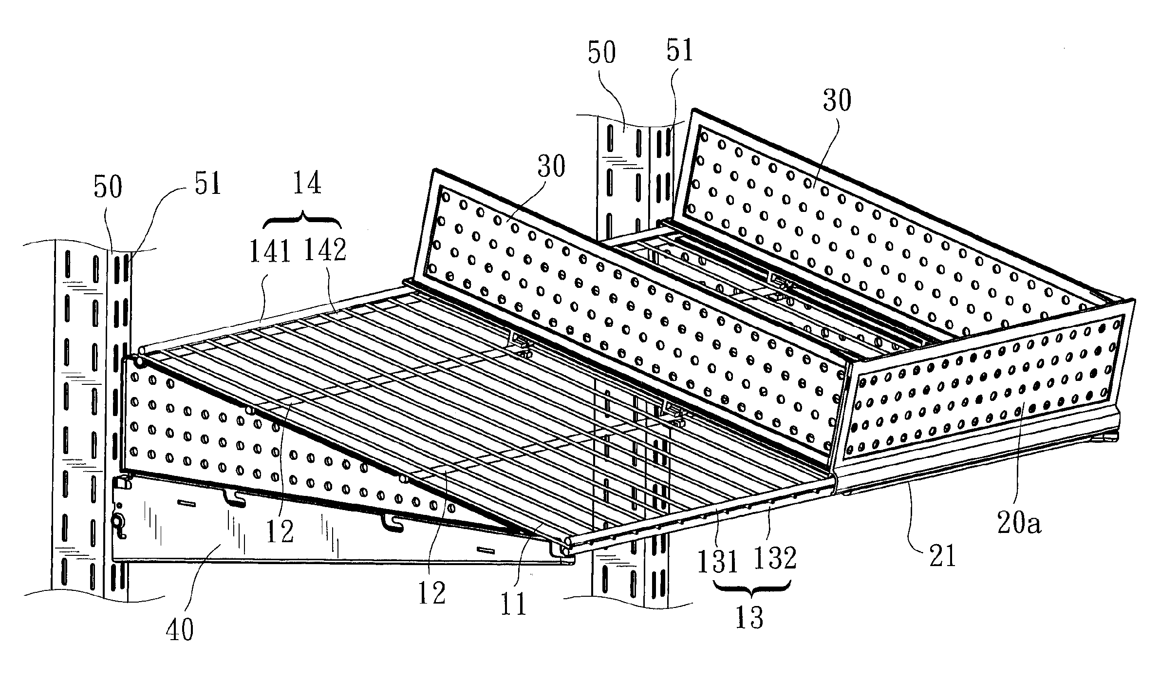
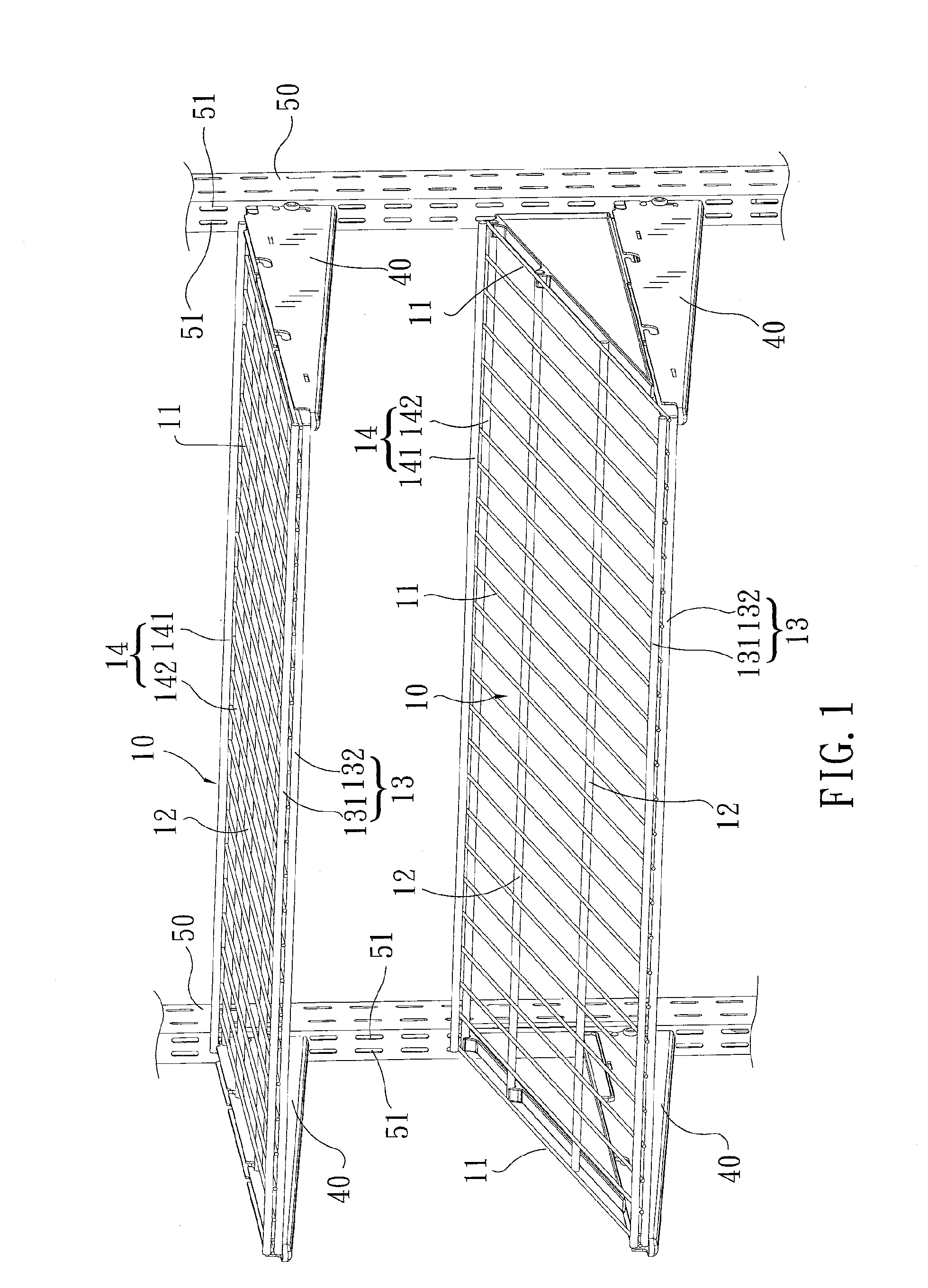
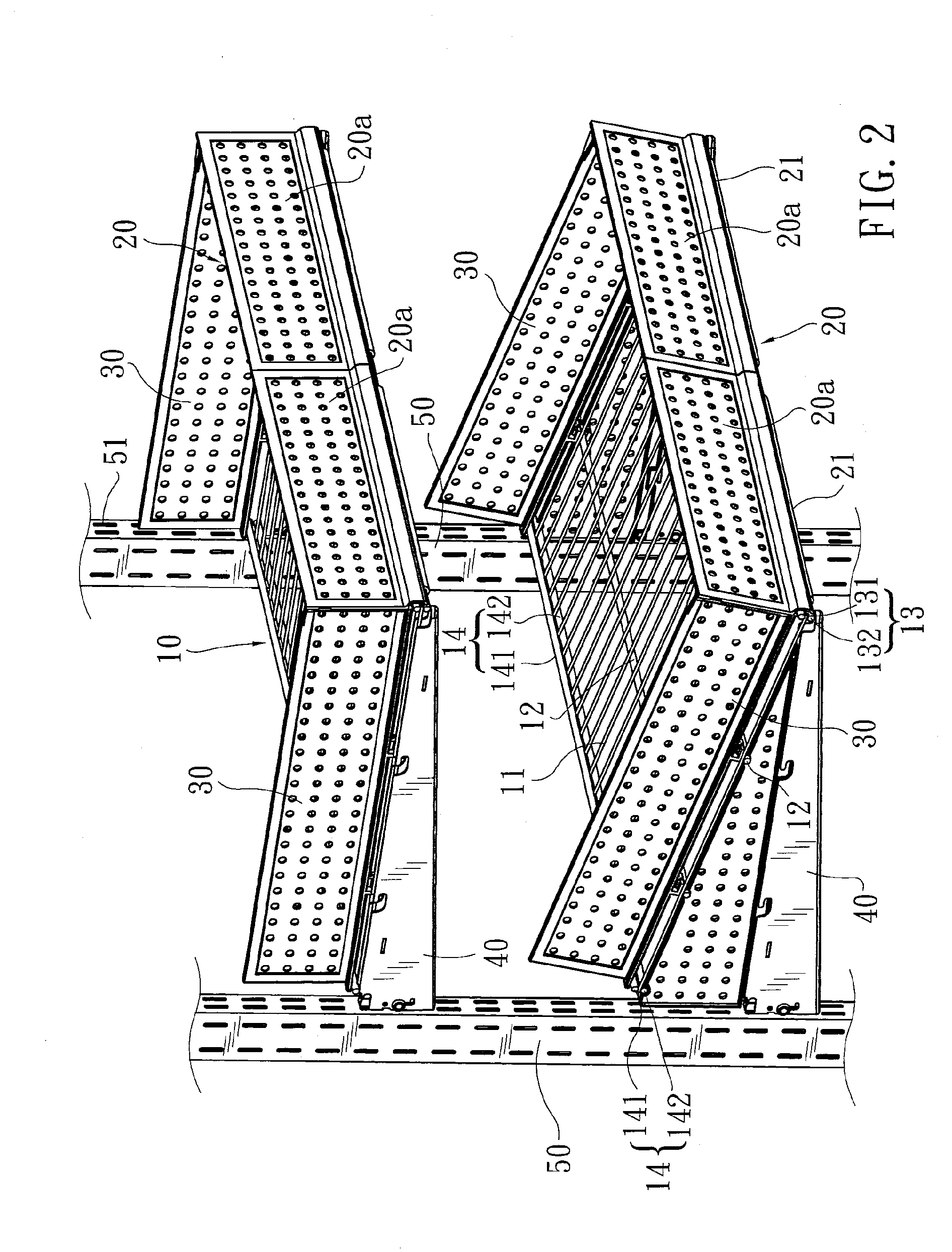
[0022]Please refer to FIG. 2. The present invention provides a stop wall structure for removably mounting to a metal-wire shelf 10 supported on, for example, a sectional rack, so that stop walls are raised from a front and two lateral edges of the metal-wire shelf 10 to protect articles positioned on the metal-wire shelf 10 against undesirable falling therefrom. As can be seen from FIG. 2, the stop wall structure of the present invention includes a front stop wall 20 for mounting to the front edge of the metal-wire shelf 10 and two side stop walls 30 for mounting to two lateral edges of the metal-wire shelf 10. The metal-shelf 10 illustrated in FIG. 2 is similar to that shown in FIG. 1, and is formed by welding a plurality of longitudinally extended metal wires 11 to a plurality of transversely extended intermediate metal bars 12, a front metal-bar set 13, and a rear metal-bar set 14, so that the metal wires 11 and the metal bars 12, 13, 14 intersect at a right angle. The front meta...


PUM


Abstract

A stop wall structure includes a front stop wall and two side stop walls for removably mounting to a front edge and two lateral edges of a metal-wire shelf for a sectional rack. The front stop wall is formed along a lower edge with a tongue portion and a plurality of clamping member spaced behind the tongue portion, so that a retaining space is formed between the tongue portion and the clamping members for engaging with a transverse front metal-bar set of the metal-wire shelf therein. The side stop walls each are provided along a lower edge with a plurality of C-shaped clamping members for each receiving and holding a transverse metal bar of the metal-wire shelf therein. With the stop wall structure mounted to the metal-wire shelf, articles positioned on the metal-wire shelf are protected against falling therefrom.

Description

FIELD OF THE INVENTION[0001]The present invention relates to a stop wall structure for removably mounting to a front and two lateral sides of a metal-wire shelf for, for example, a sectional rack, so that articles positioned on the metal-wire shelf are protected against undesirable falling therefrom.BACKGROUND OF THE INVENTION[0002]In a sectional metal rack, metal-wire shelves are often used to hold different articles thereon. As can be seen from FIG. 1, a conventional sectional metal rack includes at least two vertical posts 50 having two vertical rows of hanging holes 51 provided on each face thereof, and a plurality of metal-wire shelves 10 removably supported on and between the vertical posts 50 via supporting brackets 40 hooked to the hanging holes 51.[0003]The metal-shelf 10 is formed by welding a plurality of longitudinally extended metal wires 11 to a plurality of transversely extended intermediate metal bars 12, a front metal-bar set 13, and a rear metal-bar set 14, so that...

Claims


Application Information

Patent Timeline
Patent Type & Authority Applications(United States)
IPC IPC(8): A47F5/00
CPCA47F5/0043A47B96/021
Inventor CHEN, HENRY
Owner PROTREND ENTERPRISE CO LTD
Why Eureka
Try Eureka