Vane rotary compressor

a compressor and rotary technology, applied in the direction of machines/engines, rotary/oscillating piston pump components, liquid fuel engines, etc., can solve the problems of increased torque of the rotary shaft of the compressor, increased consumption power (hp) of the compressor, and generated chattering nois

Active Publication Date: 2014-06-19
HANON SYST
View PDF4 Cites 8 Cited by
  • Summary
  • Abstract
  • Description
  • Claims
  • Application Information

AI Technical Summary

Problems solved by technology

Accordingly, this results in an increase in consumption power (HP) of the compressor.
Therefore, this causes an increase in torque of the rotary shaft of the compressor.
In addition, in a case in which refrigerant discharge pressure is not properly formed in the initial stage of driving the compressor, since the pressure of separated oil is low and thus force to push the vane 4 from the back pressure chamber 20 is insufficient, chattering noise is generated while the front end portion of the vane 4 discontinuously rubs against the inner peripheral surface of the cylinder 1.
Moreover, a distance by which the conventional linear vane emerges from the vane slot is limited.
When a rotor 2′ comes into contact with an inner peripheral surface of a cylinder 1′ at two points in the oval cylinder 1′ having a hollow, a compression stroke is short, thereby affecting consumption power (HP), reducing a coefficient of performance (COP) of the compressor, and directly affecting fuel efficiency of a vehicle.
In addition, similarly as described in an example of one stroke compressor of FIGS. 1 and 2, there are problems in that chattering noise is generated due to a strike of a vane 4′ in the initial stage of driving the compressor, excessive force is concentrated on a point at which a front end portion of the vane 4′ comes into contact with the inner peripheral surface of the cylinder 1′ to thereby increase torque of a rotary shaft 5′, and high pressure oil must be continually supplied to a back pressure chamber 20′ to thereby increase consumption power (HP) of the compressor.

Method used


Image

  • Vane rotary compressor
  • Vane rotary compressor
  • Vane rotary compressor

Examples


an embodiment

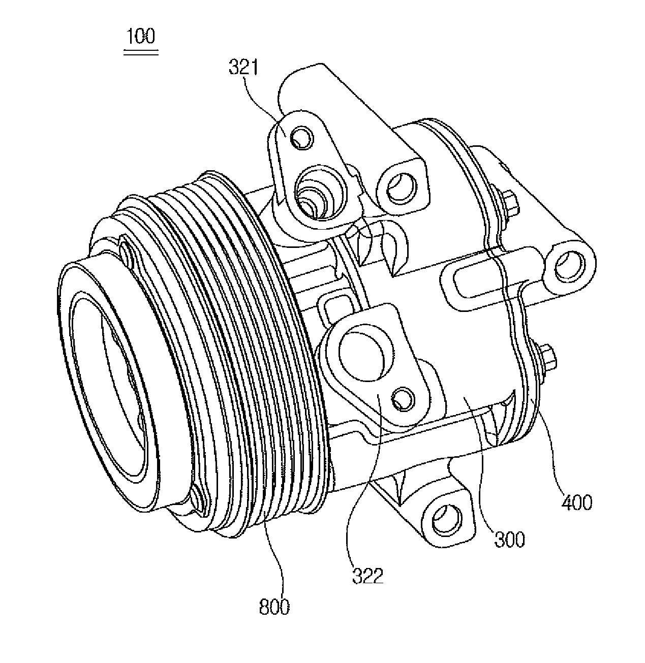
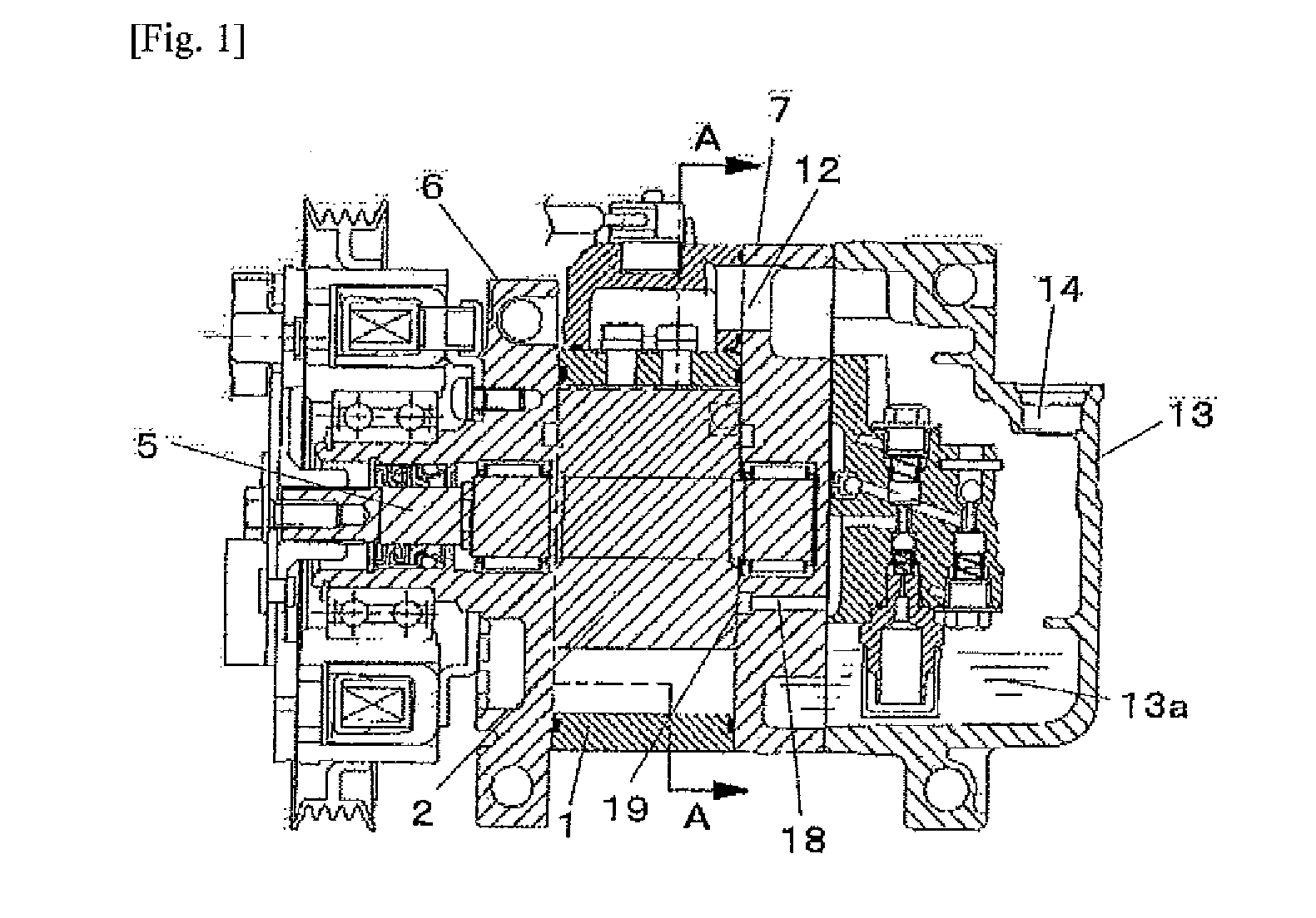
[0047]FIG. 4 is a perspective view illustrating a vane rotary compressor according to an embodiment of the present invention. FIG. 5 is a longitudinally cross-sectional view illustrating the vane rotary compressor according to the embodiment of the present invention.

[0048]As shown in FIGS. 4 and 5, a vane rotary compressor 100 according to an embodiment of the present invention includes a front housing 300 which is opened at the rear thereof so as to accommodate a cylinder 200 therein, and a rear hosing 400 which is coupled to a rear end of the front housing 300 to close an open portion of the front housing 300, thereby allowing the overall external appearance thereof to be defined.

[0049]The front housing 300 includes a cylindrical cylinder portion 310 which is formed therein with a space portion, and a head portion 320 which is formed integrally with the cylinder portion 310 in the axial front thereof to close the front of the space portion. The space portion is mounted with a holl...


PUM


Abstract

The present invention relates to a vane rotary compressor in which, while a rotor is rotating, the volume of a compressing chamber is reduced and a fluid such as a refrigerant is compressed. The vane rotary compressor according to one embodiment of the present invention is provided with the compressing chamber, the inner circumferential surface of which is formed in the shape of an involute curve, wherein the rotor is hinge-coupled with a plurality of cantilever vanes such that compression efficiency is high and noise is prevented from occurring during the operation of the compressor.

Description

TECHNICAL FIELD[0001]The present invention relates to a vane rotary compressor in which a fluid such as refrigerant is compressed while a volume of a compression chamber is reduced during rotation of a rotor, and more particularly, to a vane rotary compressor including a compression chamber which an inner peripheral surface thereof is formed in the form of an involute curve, wherein the rotor is hinge-coupled with a plurality of cantilever vanes.BACKGROUND ART[0002]A vane rotary compressor is used for an air conditioner and the like and compresses a fluid such as refrigerant so as to supply the compressed fluid to the outside.[0003]FIG. 1 is a cross-sectional view schematically illustrating a conventional vane rotary compressor disclosed in Japanese Unexamined Patent Application Publication No. 2009-07937 (Patent Document 1). FIG. 2 is a cross-sectional view taken along line A-A in FIG. 1.[0004]As shown in FIGS. 1 and 2, the conventional vane rotary compressor includes a hollow cyli...

Claims


Application Information

Patent Timeline
Patent Type & Authority Applications(United States)
IPC IPC(8): F04C15/00F04C2/44
CPCF01C21/10F01C21/106F04C18/344F04C29/065F04C29/066F04C29/02F01C1/44F04C2/44
Inventor KWAK, JUNG MYUNGHONG, SEON JOOLIM, KWEON SOOSHIN, IN CHEOL
Owner HANON SYST
Why Eureka
Try Eureka