Pressure sensor

Inactive Publication Date: 2006-03-21
YAMATAKE HONEYWELL CO LTD
View PDF15 Cites 10 Cited by
  • Summary
  • Abstract
  • Description
  • Claims
  • Application Information

AI Technical Summary

Problems solved by technology

In this manner, as the conventional pressure sensor has a complicated structure, its package becomes undesirably large.
When the differential pressure sensor and static pressure sensor are integrally formed on one chip, the manufacture becomes difficult and the cost increases.
When, however, the thickness of the diaphragm of the differential pressure sensor and that of the static pressu

Method used


Image

  • Pressure sensor
  • Pressure sensor
  • Pressure sensor

Examples


Embodiment Construction

[0016]The present invention will be described in detail with reference to the drawings.

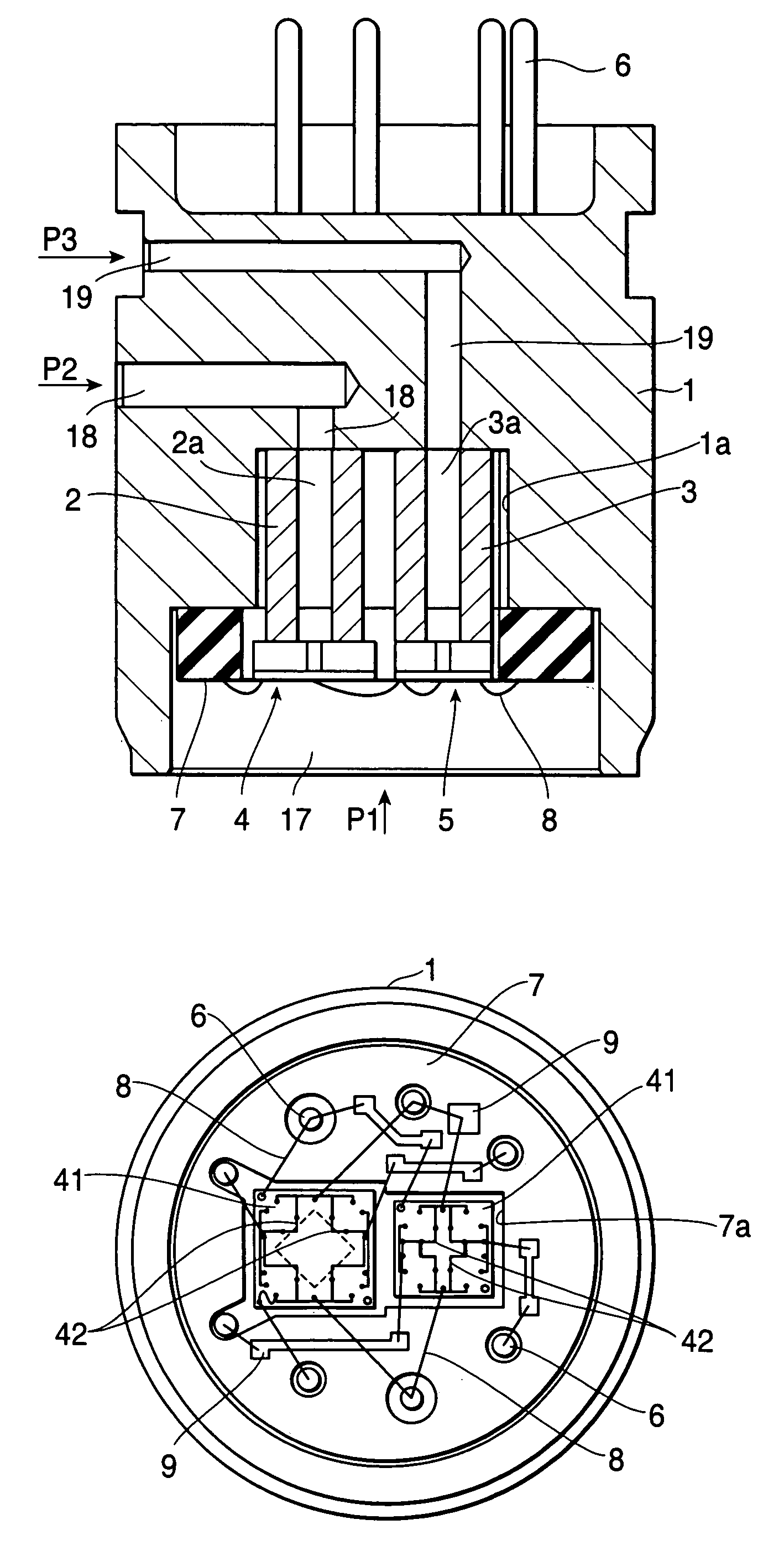
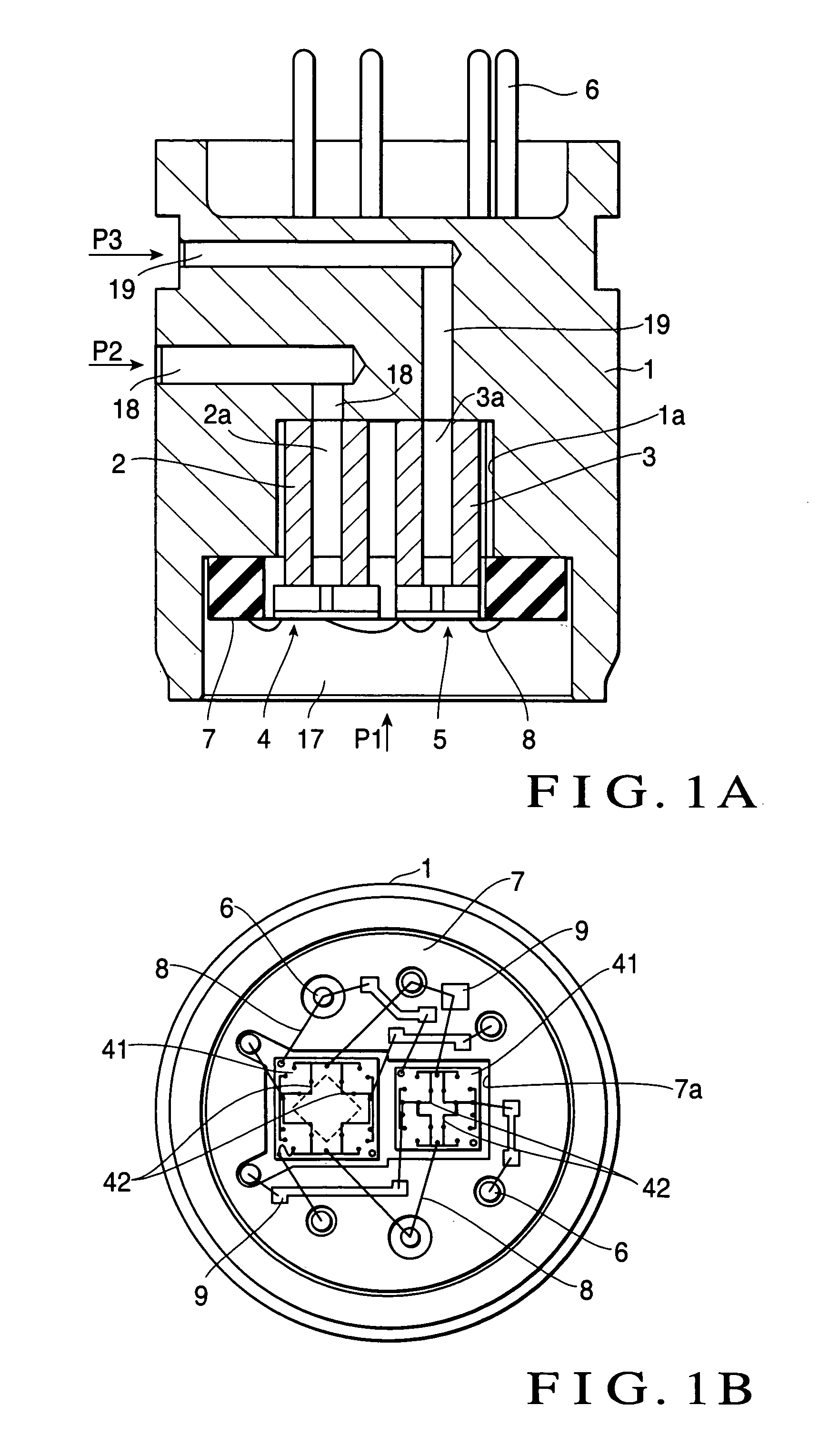
[0017]FIGS. 1A and 1B show a pressure sensor according to an embodiment of the present invention. As shown in FIG. 1B, the pressure sensor of this embodiment has a columnar header 1 serving as a base having a stepped recess 1a, first and second prismatic first pedestals 2 and 3 bonded and fixed to the bottom surface of the recess 1a of the header 1 side by side, a differential pressure measuring differential pressure sensor chip 4 bonded and fixed on the first pedestal 2, a static pressure measuring static pressure sensor chip 5 bonded and fixed on the second pedestal 3, a plurality of sensor output pins 6 for guiding electrical signals from the sensor chips 4 and 5 to the outside, a circular disk-like ceramic board 7 with a surface where wiring patterns 9 (FIG. 1B) to electrically connect the sensor chips 4 and 5 to the sensor output pins 6 are formed, and a plurality of wires 8 for connecting th...


PUM


Abstract

A differential pressure sensor chip (4) comprises a diaphragm for measuring a differential pressure and converts a pressure received by the diaphragm for measuring the differential pressure into an electrical signal. A static pressure sensor chip (5) comprises a diaphragm for measuring a static pressure and converts a pressure received by the diaphragm for measuring the static pressure into an electrical signal. The differential pressure sensor chip (4) and static pressure sensor chip (5) are mounted on a header (1) so that one surface of the differential pressure sensor chip (4) and one surface of the static pressure sensor chip (5) are exposed to the interior of a common pressure introducing chamber (17).

Description

[0001]The present application is a non-provisional application of International Application No. PCT / JP02 / 07806, filed Jul. 31, 2002.BACKGROUND OF THE INVENTION[0002]The present invention relates to a pressure sensor in which a differential pressure sensor chip for measuring a differential pressure and a static pressure sensor chip for measuring a static pressure are stored in one package.[0003]Conventionally, as a method of measuring the flow rate of a fluid, a method is available with which a pressure difference between the upstream and downstream of a restrictor is measured by utilizing the fact that the pressure difference between the upstream and downstream of the restrictor provided to a flow channel is proportional to the flow velocity, and is converted into a flow rate. With a liquid level indicator, the pressure difference between the upper and lower portions of a tank is measured, and a liquid level with a liquid density being taken into consideration is measured from the p...

Claims


Application Information

Patent Timeline
IPC IPC(8): G01L9/00G01L13/00G01L13/02G01L15/00
CPCG01L15/00G01L13/025
Inventor MIYAZAWA, KEIJI
Owner YAMATAKE HONEYWELL CO LTD
Why Eureka
Try Eureka