Dynamic quantity sensor and dynamic quantity sensor system

a sensor system and dynamic quantity technology, applied in the direction of acceleration measurement in multiple dimensions, instruments, force/torque/work measurement, etc., can solve the problems of low detection accuracy, etc., and achieve low detection accuracy, poor linearity of outputs, and low detection accuracy.

Active Publication Date: 2014-05-22
TOYOTA CENT RES & DEV LAB INC +2
View PDF4 Cites 38 Cited by
  • Summary
  • Abstract
  • Description
  • Claims
  • Application Information

AI Technical Summary

Benefits of technology

[0008]A scheme 1 is the scheme to simply detect capacity change between a movable electrode and a fixed electrode, a scheme 2 is the scheme to deduct a basic capacity from a capacity of the movable electrode, with a capacity of a reference electrode being set as the basic capacity, and a scheme 3 is the scheme (differential detection scheme) to calculate a difference of capacities of both sides of the movable electrode. Although structures become simpler as the scheme is the former one, there are such problems that a good temperature characteristic is hard to secure since the structures are subjected to an effect of offset, and that detection accuracy is low since linearity of outputs is hard to keep.
[0009]Namely, as shown in FIG. 25, with the scheme without a differential as the scheme 1, detection accuracy is the lowest since an offset capacity is large, and linearity of the outputs is poor. With the scheme using a reference electrode as the scheme 2, detection accuracy is higher than the scheme 1 since the offset capacity is small, and linearity of the outputs is better than in the scheme 1. With the differential detection scheme as the scheme 3, detection accuracy is the highest since the offset capacity is small, a good temperature characteristic can be secured because of a symmetrical structure of electrodes that perform differential as compared with the scheme 2, and linearity of the outputs is better than the scheme 2. It is to be noted that while two conductor layers are needed in the schemes 1 and 2, three conductor layers are generally needed in the scheme 3, the conductor layers serving as electrodes.

Problems solved by technology

Although structures become simpler as the scheme is the former one, there are such problems that a good temperature characteristic is hard to secure since the structures are subjected to an effect of offset, and that detection accuracy is low since linearity of outputs is hard to keep.
Namely, as shown in FIG. 25, with the scheme without a differential as the scheme 1, detection accuracy is the lowest since an offset capacity is large, and linearity of the outputs is poor.
There is a problem that since a conventional sensor described in Japanese Unexamined Patent Application Publication No. 2004-61280 can detect forces (Fx, Fy, Fz) in a triaxial direction, but highly accurate detection as differential detection cannot be performed to the force Fz in a Z direction (vertical direction), detection accuracy of a Z axis is low.

Method used


Image

  • Dynamic quantity sensor and dynamic quantity sensor system
  • Dynamic quantity sensor and dynamic quantity sensor system
  • Dynamic quantity sensor and dynamic quantity sensor system

Examples


embodiment 1

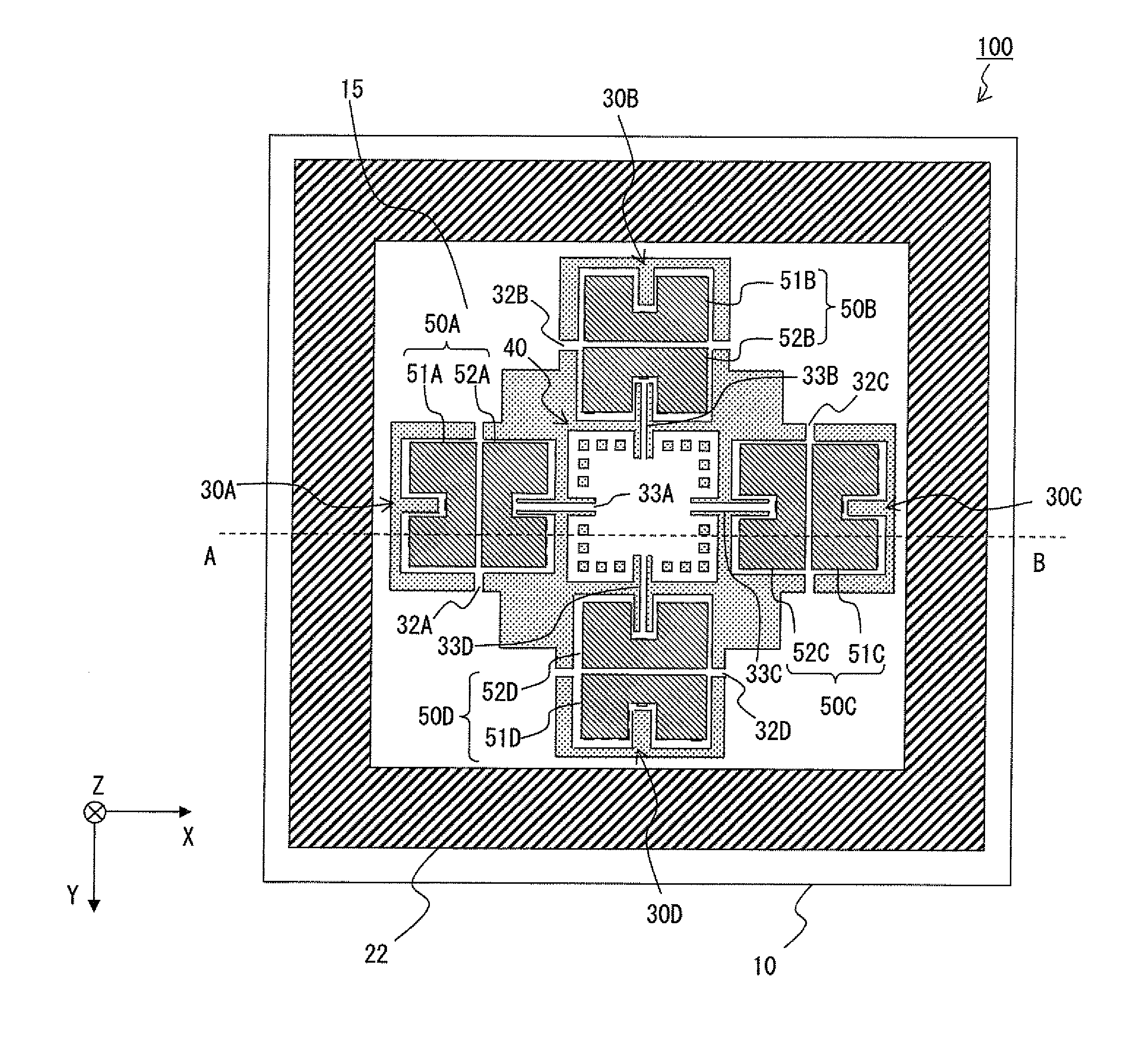
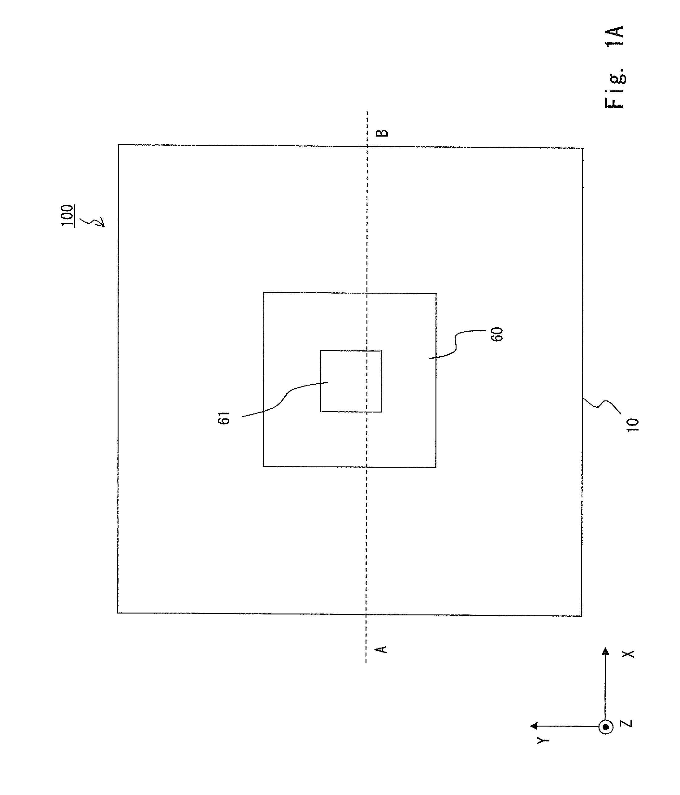
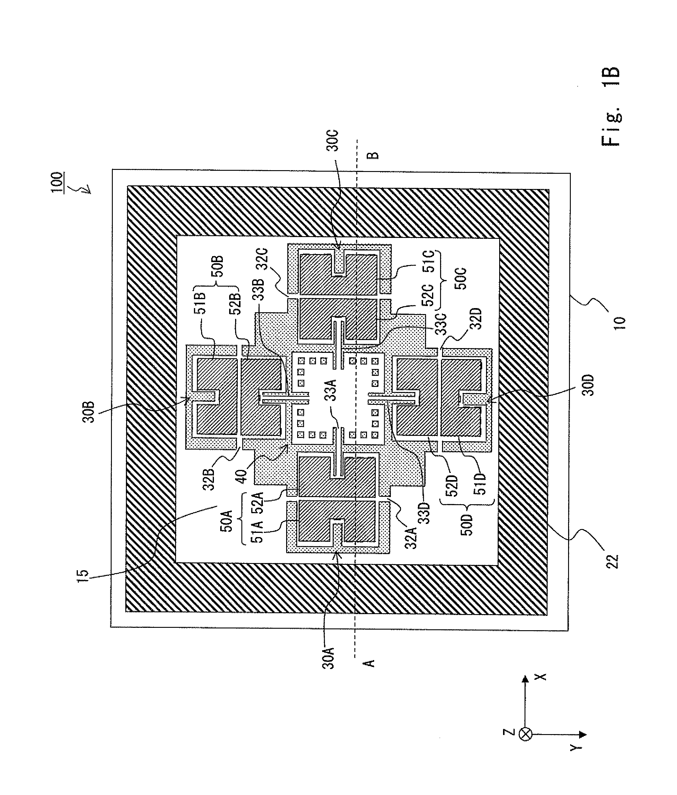
[0063]Hereinafter, an embodiment 1 will be explained with reference to the drawings. The embodiment is an example of a force sensor that detects a force, which is one of dynamic quantity, by triple axes as a multiaxial dynamic quantity sensor. The triaxial force sensor can detect forces in an X direction, a Y direction, and a Z direction. FIG. 1A is a top view of a force sensor 100 pertaining to an embodiment of the present invention. FIG. 1B is a perspective view of a bottom surface of the force sensor 100 in which a sealing substrate has been omitted. FIG. 1C is a perspective view of the bottom surface of the force sensor 100 in which the sealing substrate and a fixed electrode have been omitted. FIG. 1D is a cross-sectional side view taken along a line A-B of the force sensor 100 in FIG. 1A.

[0064]As shown in FIGS. 1A to 1D, the force sensor 100 pertaining to the embodiment is provided with a movable support portion 10 and a sealing portion 20, and the movable support portion 10 a...

embodiment 2

[0126]Hereinafter, an embodiment 2 will be explained with reference to the drawings. The embodiment is an example where the force sensor includes only a movable support portion with respect to the embodiment 1. FIG. 6A is a top view of the force sensor 100 pertaining to the embodiment. FIG. 6B is a cross-sectional side view taken along the line A-B of the force sensor 100 in FIG. 6A.

[0127]As shown in FIGS. 6A and 6B, the force sensor 100 according to the embodiment does not have a sealing portion, but is provided with only the movable support portion 10. In addition, since a force is applied from a side (main surface side) on which a force receiving portion and a seesaw portion are arranged, a force applying direction (orientation of the Z direction) is opposite as compared with the embodiment 1.

[0128]The movable support portion 10 is mainly provided with the seesaw portions 30A to 30D, the force receiving portion 40, and the fixed electrode pairs 50A to 50D, and is not provided wit...

embodiment 3

[0136]Hereinafter, an embodiment 3 will be explained with reference to the drawings. The embodiment is an example where the force sensor includes three seesaw portions with respect to the embodiment 2. FIG. 8A is a top view of the force sensor 100 pertaining to the embodiment. FIG. 8B is a cross-sectional side view taken along the line A-B of the force sensor 100 in FIG. 8A.

[0137]As shown in FIGS. 8A and 8B, the force sensor 100 according to the embodiment is provided with only the movable support portion 10 similarly to the embodiment 2. The movable support portion 10 is mainly provided with the seesaw portions 30A to 30C, the force receiving portion 40, and the fixed electrode pairs 50A to 50C. The movable support portion 10 is provided with the first silicon layer 11, the insulator film 12, and the second silicon layer 13. At the second silicon layer 13, the force receiving portion 40 is formed in a center, and the three seesaw portions 30A to 30C are formed around the force rece...


PUM

PropertyMeasurementUnit
forceaaaaaaaaaa
flexibleaaaaaaaaaa
thicknessaaaaaaaaaa

Abstract

A dynamic quantity sensor includes a force receiving portion, a first movable portion that rotates in a first rotational direction around a first rotational axis according to dynamic quantity in a first direction that the force receiving portion receives, and rotates in the first rotational direction around the first rotational axis according to dynamic quantity in a second direction different from the first direction that the force receiving portion receives; and a second movable portion that rotates in a second rotational direction around a second rotational axis according to the dynamic quantity in the first direction that the force receiving portion receives, and rotates in an opposite direction to the second rotational direction around the second rotational axis according to the dynamic quantity in the second direction that the force receiving portion receives.

Description

INCORPORATION BY REFERENCE[0001]This application is based upon and claims the benefit of priority from Japanese patent application No. 2012-252600, filed on Nov. 16, 2012, and Japanese patent application No. 2013-109119, filed on May 23, 2013, the disclosure of which is incorporated herein in its entirety by reference.BACKGROUND OF THE INVENTION[0002]1. Field of the Invention[0003]The present invention relates to a dynamic quantity sensor and a dynamic quantity sensor system and, in particular, to a dynamic quantity sensor and a dynamic quantity sensor system that are provided with a movable portion that can move according to dynamic quantity.[0004]2. Description of Related Art[0005]Conventionally, a force sensor that detects a force, which is one of dynamic quantity, has been utilized in various systems. For example, advanced processing can be achieved by using a force sensor for a surface of a robot or the like as a tactile sensor. If the force sensor is applied to fingertips of t...

Claims


Application Information

Patent Timeline
Patent Type & Authority Applications(United States)
IPC IPC(8): G01L1/04
CPCG01L1/04G01L1/144G01L1/148G01P15/125G01P15/18G01P2015/084
Inventor HATA, YOSHIYUKINONOMURA, YUTAKAFUJIYOSHI, MOTOHIROFUNABASHI, HIROFUMIAKASHI, TERUHISAOMURA, YOSHITERUNAKAYAMA, TAKAHIROYAMAGUCHI, UIYAMADA, HITOSHITANAKA, SHUJIESASHI, MASAYOSHIMUROYAMA, MASANORIMAKIHATA, MITSUTOSHI
Owner TOYOTA CENT RES & DEV LAB INC
Why Eureka
Try Eureka