Magnetic encoder

Active Publication Date: 2014-05-15
PORTESCAP
View PDF5 Cites 7 Cited by
  • Summary
  • Abstract
  • Description
  • Claims
  • Application Information

AI Technical Summary

Benefits of technology

[0006]The present invention aims to solve these aforementioned drawbacks and is directed to an encoder having a reduced packaging compared to th

Problems solved by technology

This minimal gap has a negative impact onto the accuracy and is a limit to the reduction of the size of the encoder and of the magnet, as this magnet shall produce a minimal magnetic field greater than the Hall Effect s

Method used


Image

  • Magnetic encoder
  • Magnetic encoder
  • Magnetic encoder

Examples


Example

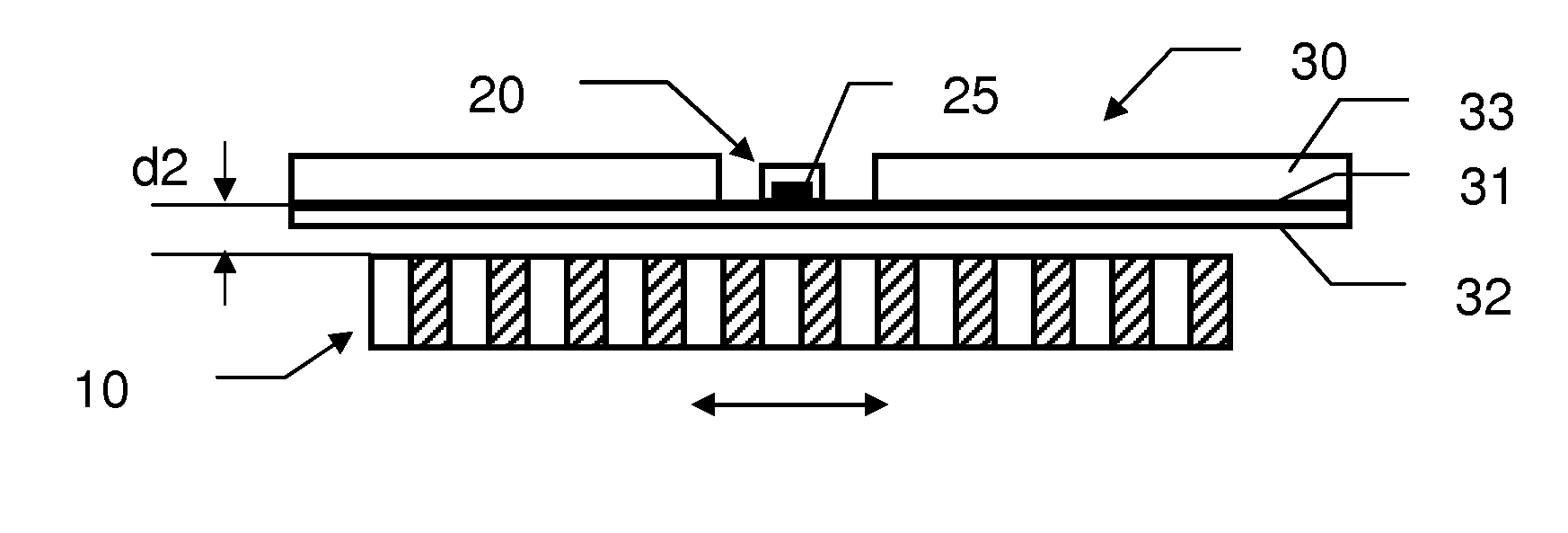
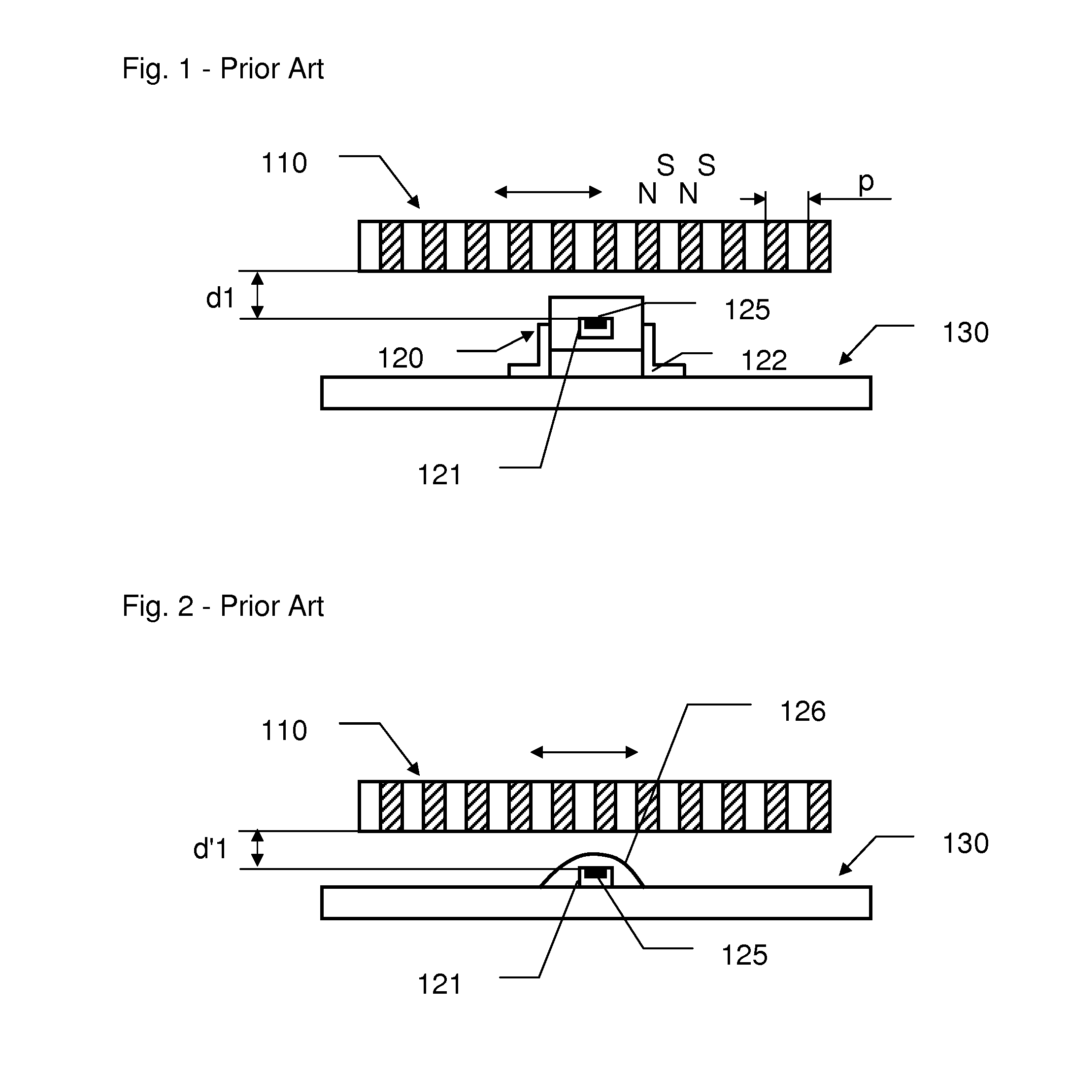
[0034]The encoder represented at FIG. 1 comprises a moveable part 110 made of an alternation of magnetic dipoles North-South as represented, defining a polar pitch p. The encoder comprises a Hall Effect sensor 120 comprise a silicon die chip 121 with a sensitive area 125 over-molded in an external case. The Hall Effect sensor 120 is mounted onto a circuit board 130 via its contact pins 122.

[0035]A movement of the moveable part 110 will create a change of the magnetic field in the vicinity of the sensitive area 125. Provided that this magnetic field is greater than the limit of detection of the Hall Effect sensor 120, the movement of the moveable part will be encoded. The distance d1 is then an important parameter in the performance of the represented encoder. It will determine the minimum limit of detection required in relation to the magnetic dipole characteristics. To reduce the packaging of the encoder and the costs of the Hall Effect sensor, it is important to lower as much as p...


PUM


Abstract

Encoder including
    • a moveable part with at least one magnetic dipole,
    • at least one Hall Effect sensor with a sensitive area arranged to detect a magnetic field created by the magnetic dipole,
    • at least one circuit board with a main thickness and having an attachment portion on which the Hall Effect sensor is mounted,
  • where the Hall Effect sensor is a semiconductor die sensor with the sensitive area arranged on an external face of the semiconductor die,
  • where the Hall Effect sensor is flip chip mounted onto the attachment portion of the circuit board, with the sensitive area in contact with the circuit board, and where the attachment portion is arranged between the Hall Effect sensor and the magnetic dipole and presents a reduced thickness compared to the main thickness of the rest of the circuit board.

Description

CROSS REFERENCE TO RELATED APPLICATION[0001]This application claims the benefit of Switzerland Patent Application Number 02382 / 12 filed on 14 Nov. 2012, the contents of which are herein incorporated by reference in their entirety.TECHNICAL FIELD[0002]The present invention relates to encoders for electric motors and especially to encoders comprising a Hall Effect sensor.BACKGROUND[0003]A typical encoder from the prior art is an encoder having a magnetic disk with a polar pitch p, attached to the rotation axis of an electric motor and a circuit board supporting one or two Hall Effect sensors in the vicinity of the magnetic disk, as represented on FIG. 1 or FIG. 2. To enhance the accuracy or resolution of such encoder, the distance between the magnetic disk and the Hall Effect sensor has to be as small as possible. However, due to production variations, and tolerances of the components, a minimal gap is required between the sensor and the magnetic disk. This minimal gap has a negative ...

Claims


Application Information

Patent Timeline
IPC IPC(8): G01R33/07H02K11/00G01B7/30
CPCG01R33/07H02K11/0021G01B7/30G01D5/145G01D11/30H02K11/215H02K29/06H02K29/08
Inventor BERNEY, JULIANBAUDEY, JULIEN
Owner PORTESCAP
Why Eureka
Try Eureka