Microwave irradiation apparatus

a technology of irradiation apparatus and microwave, which is applied in the direction of microwave heating, electrical apparatus, electric/magnetic/electromagnetic heating, etc., can solve the problems of difficulty in uniform irradiation of a plurality of samples held by the sample holder with the microwave, and the proposal of a microwave of low power suitable for this low temperature uniform heating has not yet been mad

Inactive Publication Date: 2010-12-09
PACIFIC MICROWAVE TECH
View PDF7 Cites 15 Cited by
  • Summary
  • Abstract
  • Description
  • Claims
  • Application Information

AI Technical Summary

Benefits of technology

[0008]In view of the problems encountered by the conventional technology as described above, the present invention describes a microwave irradiation apparatus capable of uniformly treating a large number of samples at the same time, and also capable of performing the automatic consecutive process as needed.

Problems solved by technology

In this case, it is difficult to uniformly irradiate a plurality of samples held by the sample holder with the microwave.
In treating samples related to biotechnology or medical care, it is necessary that the samples, each of which is in small amounts, are uniformly heated to the relatively low temperatures about 40° C. However, a microwave irradiation apparatus capable of consecutively treating a large number of samples while emitting microwave of low power suitable for this low temperature uniform heating has not yet been proposed.

Method used


Image

  • Microwave irradiation apparatus
  • Microwave irradiation apparatus
  • Microwave irradiation apparatus

Examples


Embodiment Construction

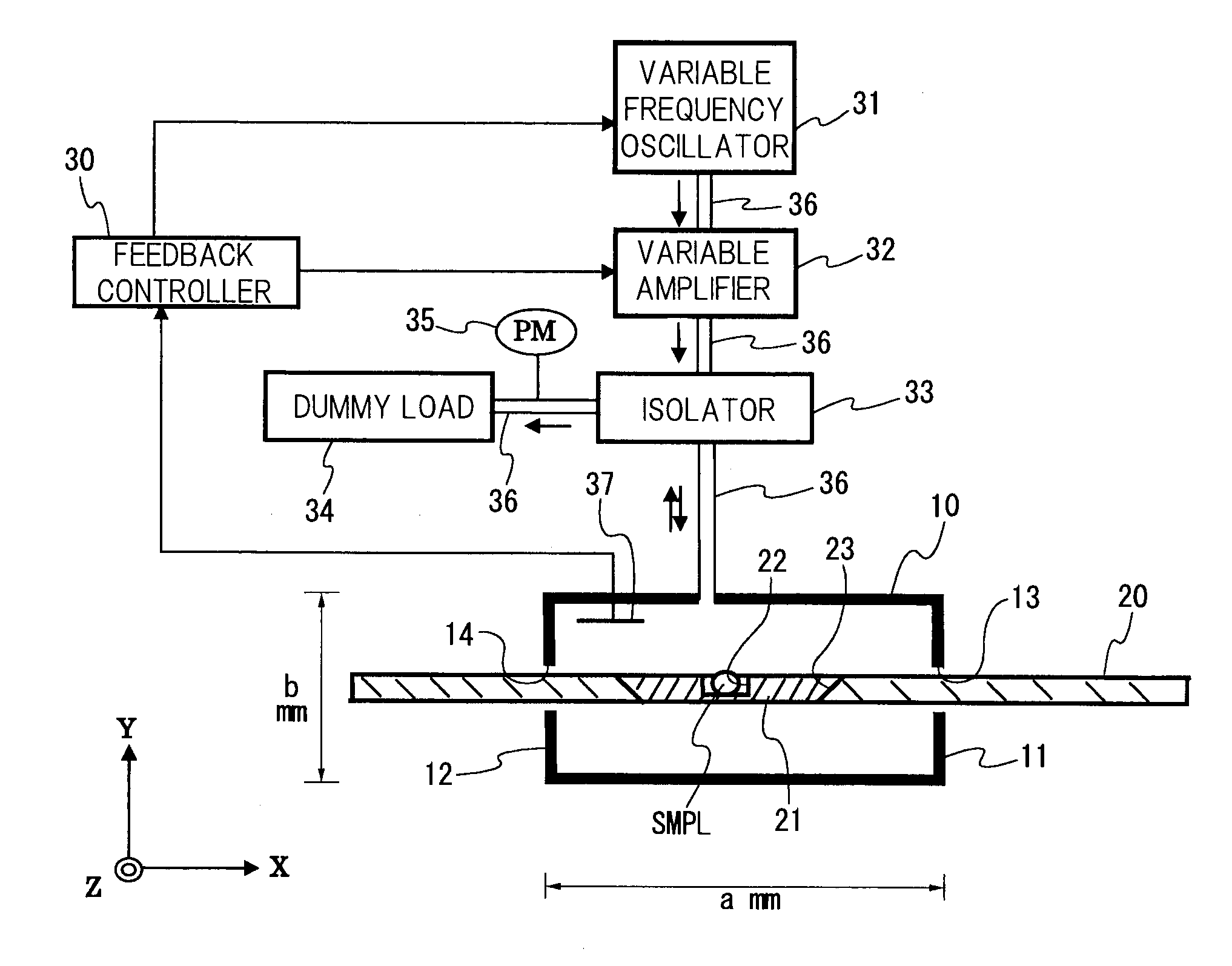
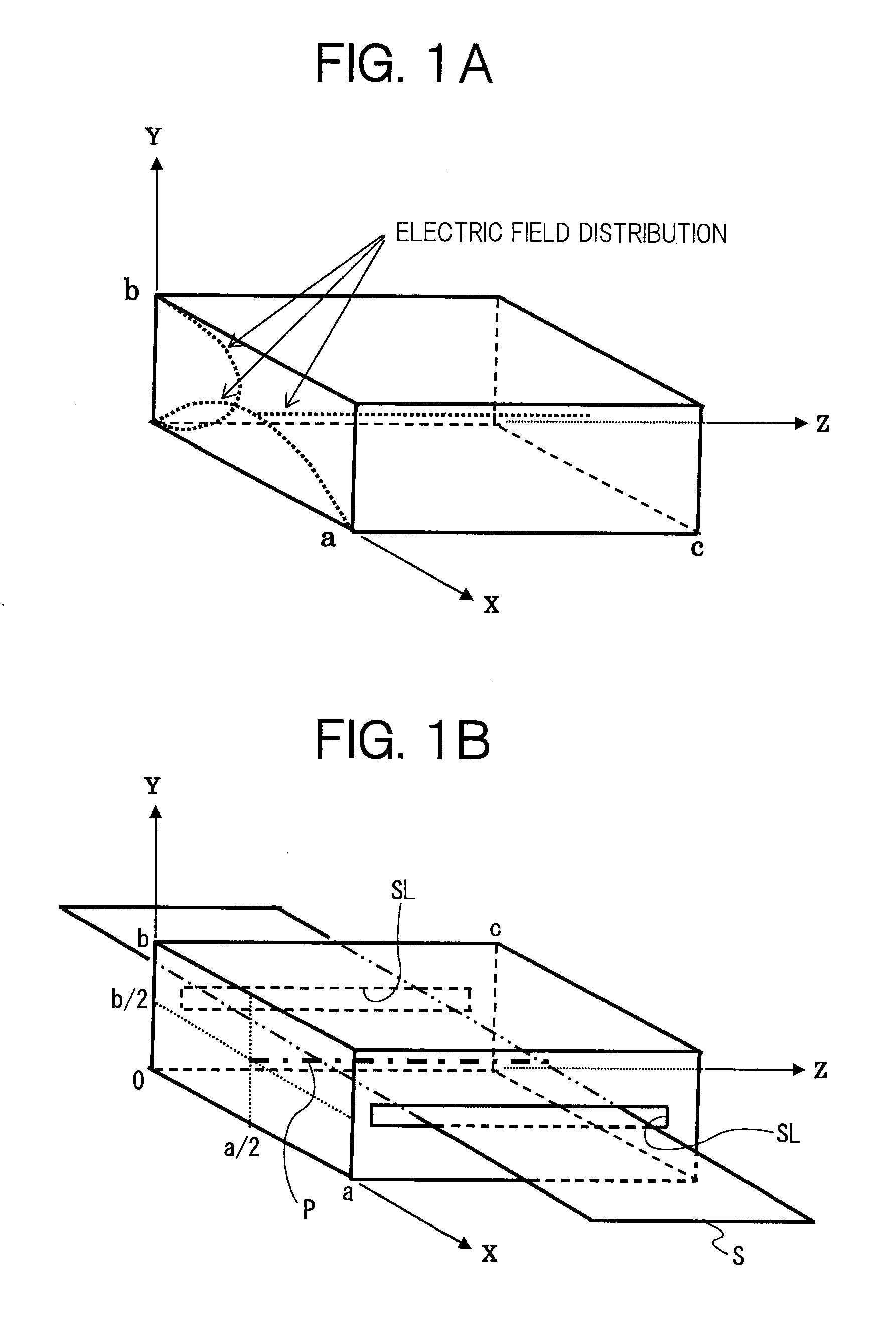
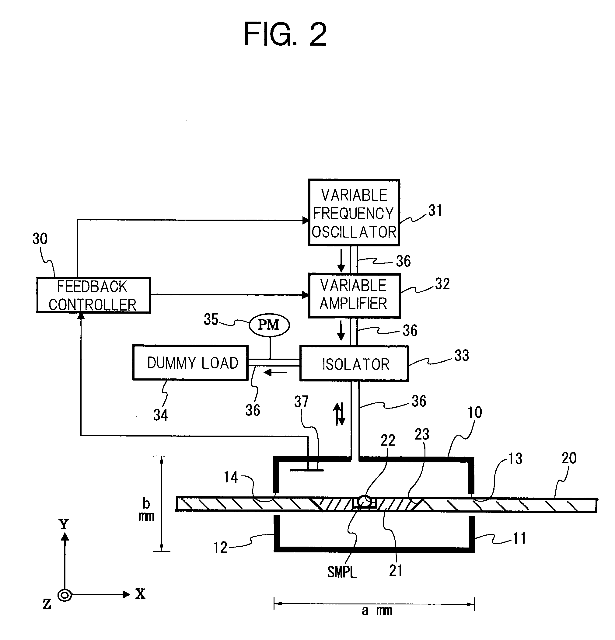
[0020]In the rectangular resonant cavity of TM 110 mode, the microwave makes an electric field distribution in the shape of sine half-wave along an X-axis and a Y-axis, and furthermore, makes a fixed electric field distribution along a Z-axis. Namely, in the irradiation chamber formed in the rectangular resonant cavity, the length “a” of X-axis side and the length “b” of Y-axis side are respectively coincident with the sine half-wave, and the fixed electric field distribution is generated along a line segment in a Z-axis direction corresponding to an arbitrary coordinate (x, y). Therefore, when samples are aligned in the Z-axis direction along the X-Z plane having a predetermined coordinate “y” in the irradiation chamber, and then the samples aligned in the Z-axis direction are transferred in an X-axis direction, the samples aligned in the Z-axis direction are efficiently and uniformly irradiated with the microwave, so that the plurality of samples can be uniformly and consecutively...


PUM


Abstract

A microwave irradiation apparatus proposed for uniformly treating a large number of samples, includes: an irradiation chamber formed in a rectangular resonant cavity of TM (Transverse Magnetic) 110 mode, of which length of X-axis side is “a” (a>0), length of Y-axis side is “b” (b>0) and length of Z-axis side is “c” (c>0); slits respectively formed on Y-Z plane walls of the irradiation chamber; a transfer sheet entering into the irradiation chamber through the slits and moving along a X-Z plane in the irradiation chamber; and a sample holder disposed on the transfer sheet.

Description

[0001]This application is a continuation of PCT / JP / 2008 / 072534, filed on Dec. 11, 2008.BACKGROUND OF THE INVENTION[0002]1. Field of the Invention[0003]The present invention relates to a microwave irradiation apparatus for irradiating an object placed in an irradiation chamber with microwave.[0004]2. Description of Related Art[0005]In recent years, in a bio-related field, the usage of microwave for sample treating has been proposed. Namely, a microwave irradiation apparatus has been proposed, in which the microwave irradiation apparatus uses a conventional microwave cooking oven treating a sample held by a sample holder placed therein. In this case, it is difficult to uniformly irradiate a plurality of samples held by the sample holder with the microwave.[0006]In the case of the conventional microwave oven, it is inevitable that a strong portion of microwave and a weak portion of microwave appear in the irradiation chamber due to the generation of standing waves. Thus, it is difficul...

Claims


Application Information

Patent Timeline
Patent Type & Authority Applications(United States)
IPC IPC(8): H05B6/68
CPCH05B6/6408H05B6/806H05B6/78
Inventor TOMITA, AKISAIDA, HISATO
Owner PACIFIC MICROWAVE TECH
Why Eureka
Try Eureka