
Device for Opening and Locking a Tail Unit for Ammunition

Inactive Publication Date: 2010-12-09
TDA ARMEMENTS
View PDF9 Cites 7 Cited by
  • Summary
  • Abstract
  • Description
  • Claims
  • Application Information

AI Technical Summary

Benefits of technology

[0007]Embodiments of the present invention advantageously provide a device for opening and locking a tail unit which is of simple design and which makes it possible to limit the clearances between the various components of the tail unit, and, in particular, to eliminate any angular clearance of the fins in the deployed position without requiring any substantial modifications to the design.

Problems solved by technology

The presence of a tail unit is notably required when the ratio of the length to the caliber of the ammunition is high, the ammunition thus not being able to stabilize gyroscopically.
Such an optimization may notably prove indispensible for guided ammunition.
As a result, said clearances impair the aerodynamic behavior of the ammunition.
In particular, they impair the guiding of guided ammunition.

Method used


Image

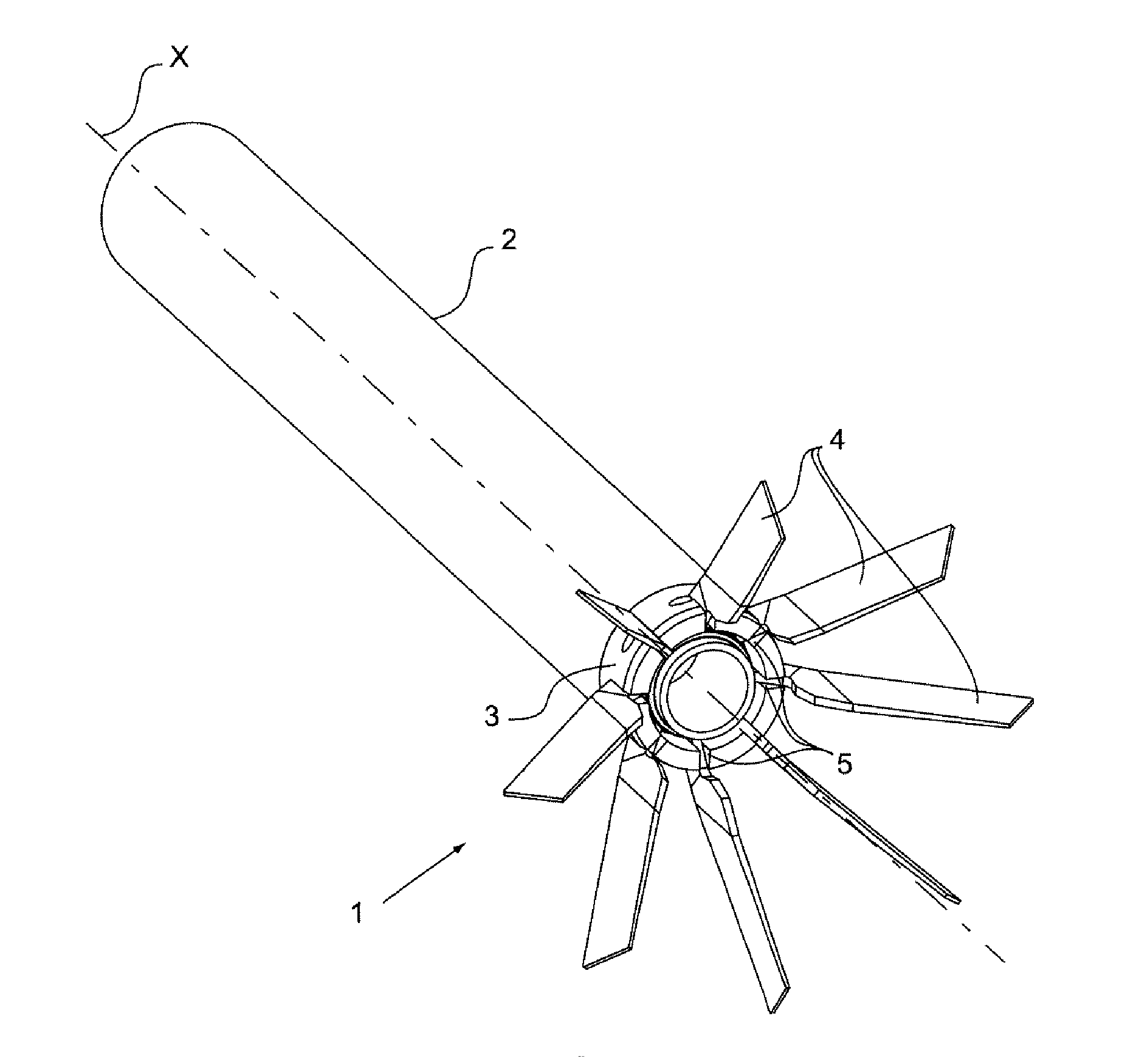
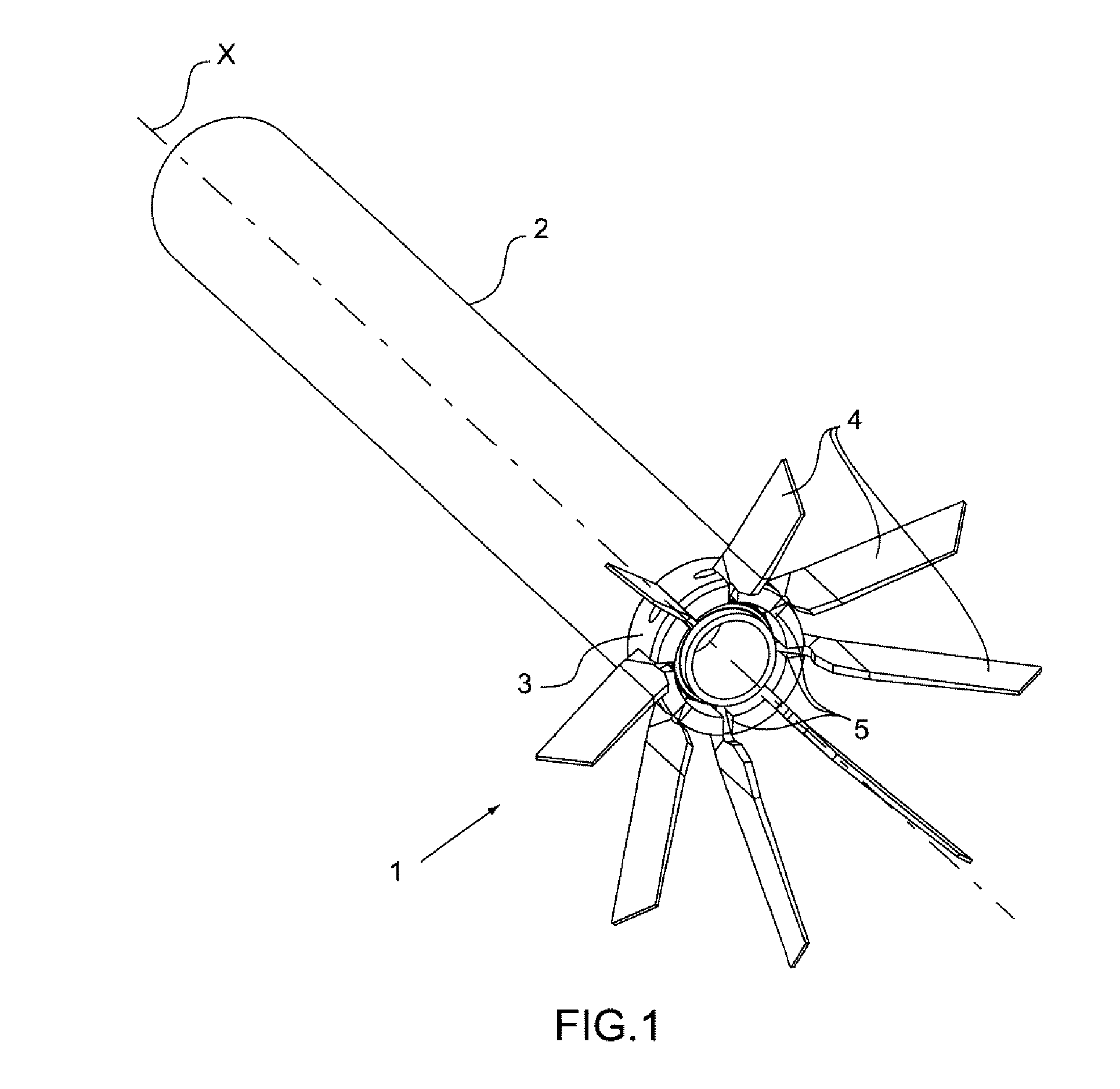
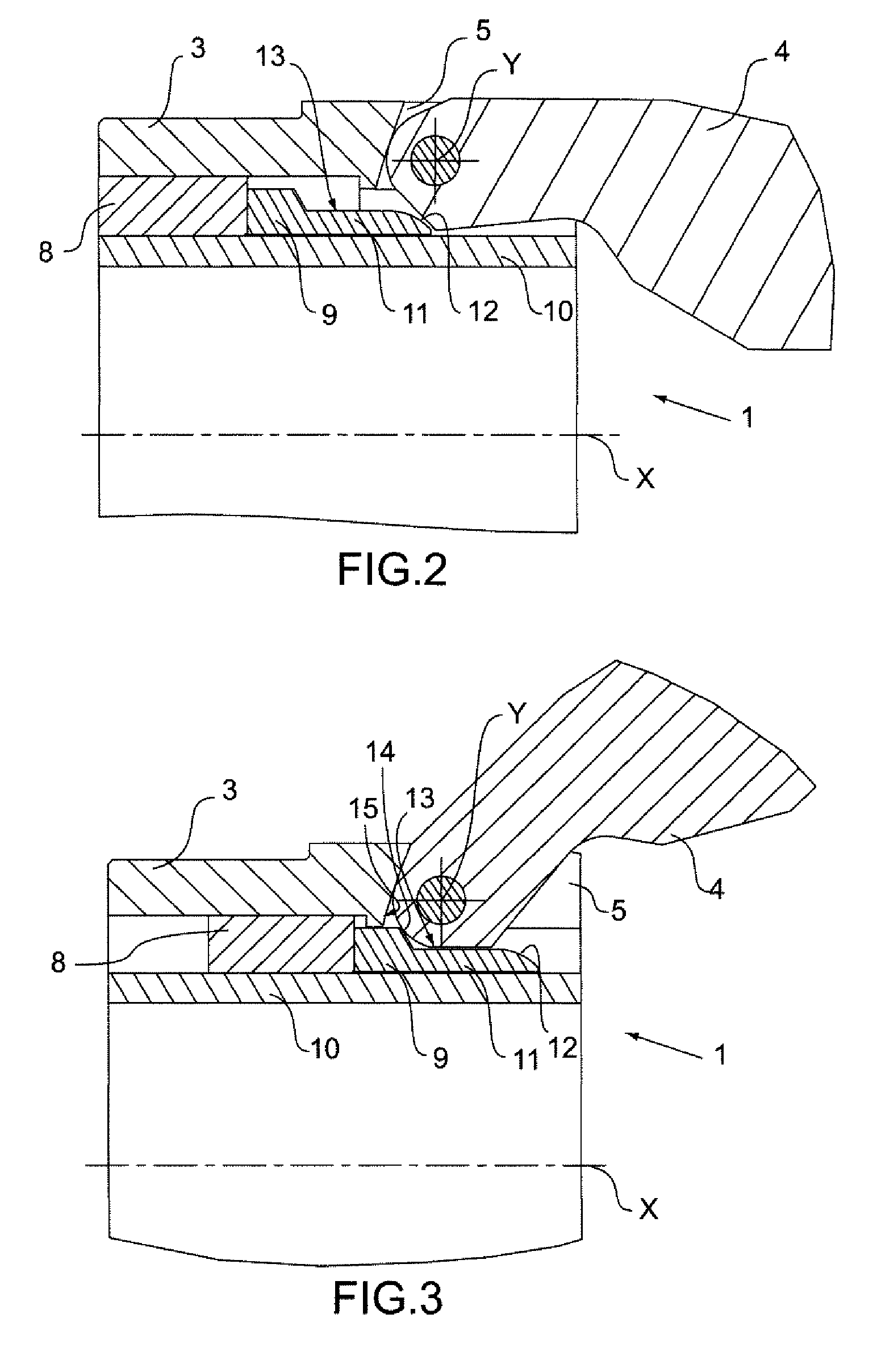
  • Device for Opening and Locking a Tail Unit for Ammunition
  • Device for Opening and Locking a Tail Unit for Ammunition
  • Device for Opening and Locking a Tail Unit for Ammunition

Examples


first embodiment

[0026]FIGS. 4 to 7 illustrate, in a view similar to that of FIG. 2, a device for opening and locking a tail unit according to the invention.

[0027]In the first instance, reference is made to FIG. 4 where the device is shown when the fin 4 is in the folded position. The device shown in FIG. 4 differs essentially from the device shown in FIGS. 2 and 3 in that the fin comprises a projection 16 protruding in the direction of the control ring 9 when the fin 4 is in the folded position and in that the component 11 has a cutting tool profile between the surface 13 and a leading surface 17, for example a bevel or a rounded portion. This cutting tool profile forms the means for shaping the projection 16. Advantageously, the material of the control ring 9 has a greater mechanical strength than that of the material of the fin 4, for example at a ratio substantially equal to three to one. By way of example, the control ring may be made of steel having a mechanical strength substantially equal to...

second embodiment

[0033]FIGS. 9 and 10 illustrate a particular embodiment of the device for opening and locking a tail unit according to the FIG. 9 shows the device in a similar view to that of FIGS. 2 to 8 and FIG. 10 shows the device in a sectional view along the sectional plane B-B of FIG. 9, the fin 4 being deployed. The device according to this particular embodiment is distinguished essentially from the device shown in FIG. 8 in that the guide 10 comprises a groove 22 oriented along the axis X and in that the control ring 9 comprises a finger 23 protruding into the groove 22. The presence of the finger 23 in the groove 22 makes it possible to reduce further the lateral clearance of the fins 4 relative to the body 3. More specifically, the finger 23, interacting with the fin 4 by means of the notches 21, forms an additional point of contact with the body 3, this point of contact being relatively remote from the lateral contact surfaces 24 and 25 of the fin 4 with the sides of the slot 5 formed i...


PUM


Abstract

A device for opening and locking a tail unit is provided. The tail unit includes a body and at least one fin, pivotable relative to the body along a first axis, that has a projection that forms an element. The device comprises a control ring, slidable relative to the body along a second axis, that includes a component, forming an element, that bears against the projection to deploy the fin, the second axis being non-parallel and non-secant to the first axis. A means for shaping one of the elements during translation along the second axis of the control ring towards the projection of the fin is provided on the other element. The body includes a bearing surface to support the fin during shaping, in which the support of the fin on the bearing surface corresponds to the deployed position of the fin.

Description

CROSS-REFERENCE TO RELATED APPLICATIONS[0001]This application claims priority to foreign Patent Application FR 09 02734, filed on Jun. 5, 2009, the disclosure of which is incorporated herein by reference in its entirety.FIELD OF THE INVENTION[0002]The invention relates to a device for opening and locking a tail unit capable of fitting any type of ammunition, such as a missile, a rocket or a projectile. The invention relates more particularly to a device for opening and locking an unfolding tail unit of the umbrella type comprising a plurality of fins. The invention also relates to ammunition comprising such a device for opening and locking a tail unit.BACKGROUND OF THE INVENTION[0003]A tail unit fitted to ammunition generally comprises a plurality of fins uniformly distributed over the periphery to the rear of the ammunition. There are many reasons which may make it necessary, or at least preferable, to provide a tail unit having a span which is greater than the caliber of the ammun...

Claims


Application Information

Patent Timeline
IPC IPC(8): F42B10/14
CPCF42B10/18
Inventor COHE, PATRICKBOISSIERE, BRUNOCLECH, LOIC
Owner TDA ARMEMENTS
Learn More