Method of manufacturing piezoelectric vibrator, piezoelectric vibrator, oscillator, electronic device, and radio clock

Inactive Publication Date: 2010-12-09
SII CRYSTAL TECH
View PDF7 Cites 18 Cited by
  • Summary
  • Abstract
  • Description
  • Claims
  • Application Information

AI Technical Summary

Benefits of technology

[0056]The piezoelectric vibrator according to the invention can be formed to be thinner and more compact than a piezoelectric vibrator in the related art.
[0057]Further, according to the method of manufacturing the piezoelectric vibrators of the invention, it may be possible to efficiently manufacture the surface mounted piezoelectric vibrators, which are made compact, at a time. Acco

Problems solved by technology

First, as electronic devices have been reduced in size in recent years, there is a demand for the further reduction in the size of the piezoelectric vibrator 200 that is mounted on various electronic devices. Meanwhile, since the piezoelectric vibrator 200 in the related art has the three-layer structure where the piezoelectric substrate 201 is interposed between the base substrate 202 and the lid substrate 203 in a vertical direction, the piezoelectric vibrator is necessarily

Method used


Image

  • Method of manufacturing piezoelectric vibrator, piezoelectric vibrator, oscillator, electronic device, and radio clock
  • Method of manufacturing piezoelectric vibrator, piezoelectric vibrator, oscillator, electronic device, and radio clock
  • Method of manufacturing piezoelectric vibrator, piezoelectric vibrator, oscillator, electronic device, and radio clock

Examples


Embodiment Construction

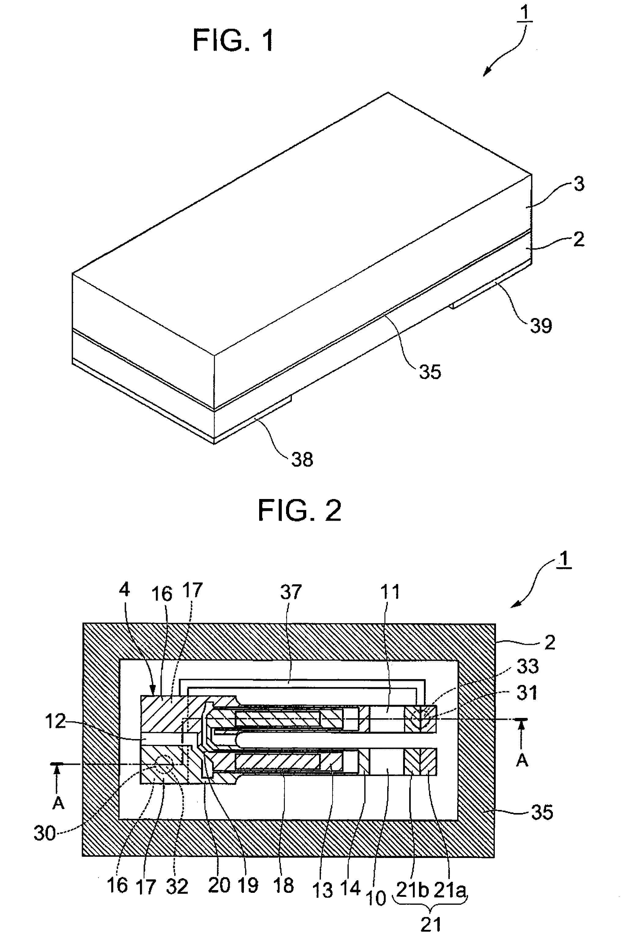
[0094]An embodiment of the invention will be described below with reference to FIGS. 1 to 17.

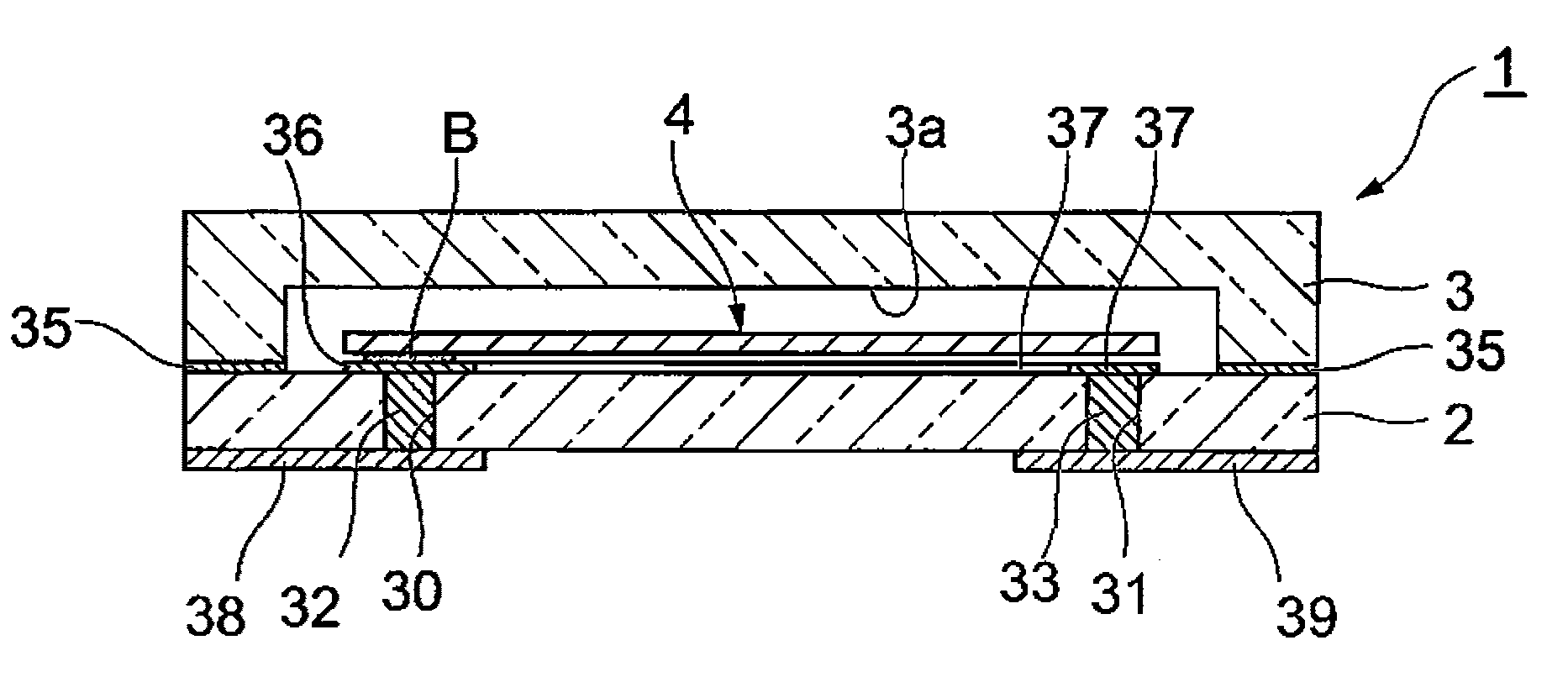
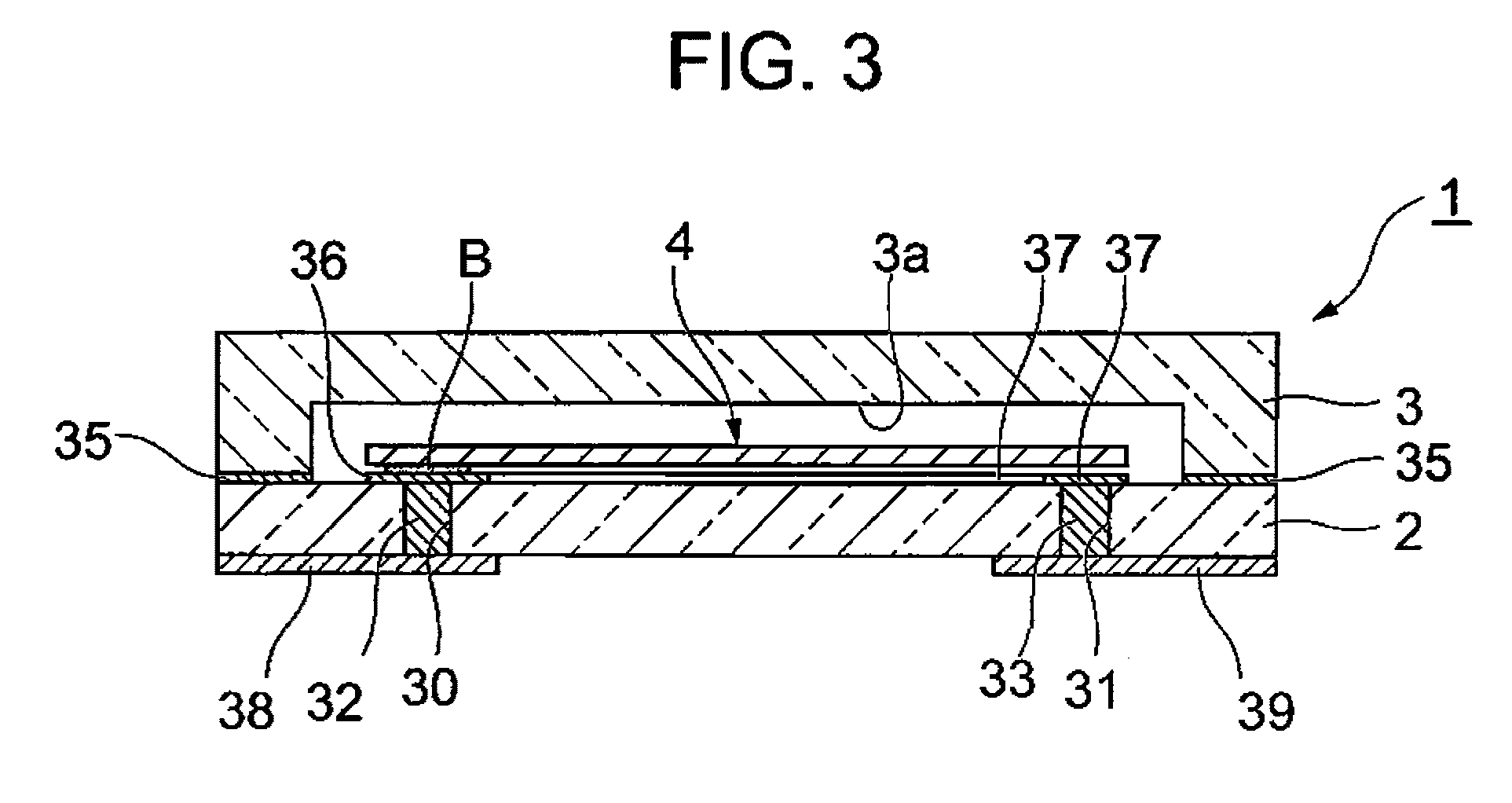
[0095]As shown in FIGS. 1 to 4, a piezoelectric vibrator 1 according to this embodiment is formed in a box shape where two layers (a base substrate 2 and a lid substrate 3) are laminated, and is a surface mounted piezoelectric vibrator where a piezoelectric vibrating reed 4 is received in an inner cavity C.

[0096]Meanwhile, for the easy understanding of drawings, an excitation electrode 15, extraction electrodes 19 and 20, mount electrodes 16 and 17, and a weight metal film 21, which are to be described below, are not shown in FIG. 4.

[0097]As shown in FIGS. 5 to 7, the piezoelectric vibrating reed 4 is a tuning-fork type vibrating reed that is made of a piezoelectric material, such as crystals, lithium tantalite, or lithium niobate. When a predetermined voltage is applied to the piezoelectric vibrating reed, the piezoelectric vibrating reed vibrates.

[0098]The piezoelectric vibrating reed 4 in...


PUM

PropertyMeasurementUnit
Timeaaaaaaaaaa
Surface roughnessaaaaaaaaaa
Mean roughnessaaaaaaaaaa

Abstract

A piezoelectric vibrator includes a base substrate, a lid substrate, a piezoelectric vibrating reed, a pair of external electrodes, a pair of through electrodes, and routing electrodes. The base substrate is made of a glass material and a bonding film is formed on the upper surface of the base substrate. The lid substrate is made of a glass material, includes a recess for a cavity, and is bonded to the base substrate with the bonding film interposed therebetween so that the recess faces the base substrate. The piezoelectric vibrating reed is bonded to the upper surface of the base substrate so as to be received in a cavity that is formed between the base substrate and the lid substrate by the recess. The pair of external electrodes is formed on the lower surface of the base substrate. The pair of through electrodes is formed so as to pass through the base substrate, maintains airtightness in the cavity, and is electrically connected to the pair of external electrodes, respectively. The routing electrodes are formed on the upper surface of the base substrate, and are electrically connected to the piezoelectric vibrating reed bonded to the pair of through electrodes.

Description

RELATED APPLICATIONS[0001]This application is a continuation of PCT / JP2008 / 065551 filed on Aug. 29, 2008, which claims priority to Japanese Application No. 2008-036423 filed on Feb. 18, 2008. The entire contents of these applications are incorporated herein by reference.TECHNICAL FIELD[0002]The present invention relates to a surface mounted (SMD) piezoelectric vibrator where a piezoelectric vibrating reed is sealed in a cavity formed between two bonded substrates, a method of manufacturing the piezoelectric vibrator, and an oscillator, an electronic device, and a radio clock that each include the piezoelectric vibrator.BACKGROUND ART[0003]In recent years, a piezoelectric vibrator, which employs crystals or the like as a time source, as a timing source of a control signal or the like, or as a reference signal source or the like, has been used in cell phones or portable information terminal devices. There are known various types of this kind of piezoelectric vibrator, and one of these...

Claims


Application Information

Patent Timeline
IPC IPC(8): H01L41/053H01L41/22
CPCH03H3/02H03H9/1021Y10T29/42H03H2003/026H03H9/21
Inventor ARATAKE, KIYOSHINUMATA, MASASHI
Owner SII CRYSTAL TECH
Why Eureka
Try Eureka