

Control device, input device, control system, handheld device, and control method
- Summary
- Abstract
- Description
- Claims
- Application Information
AI Technical Summary
Benefits of technology
Problems solved by technology
Method used
Image

Examples
first embodiment
Various Modifications of First Embodiment
[0230]With the present embodiment, description has been made wherein when the user releases the thumb from above the button 11, the first coordinate values (the coordinate values of the virtual pointer 2″) are moved to the positions of the second coordinate values (the coordinate values of the real pointer 2′). However, when the user makes the thumb enter above the button 11, the first coordinate values may be moved to the positions of the second coordinate values. The same advantage may also be obtained by such processing.
[0231]Description has been made wherein in FIG. 12, in ST209, the first coordinate values (X(t), Y(t)) (the coordinate values of the virtual pointer 2″) are moved to the second coordinate values (second coordinate values (X′(t), Y′(t))). However, the positions where the first coordinate values are moved are not restricted to these. Typically, the positions where the first coordinate values are moved may be any positions wit...
second embodiment
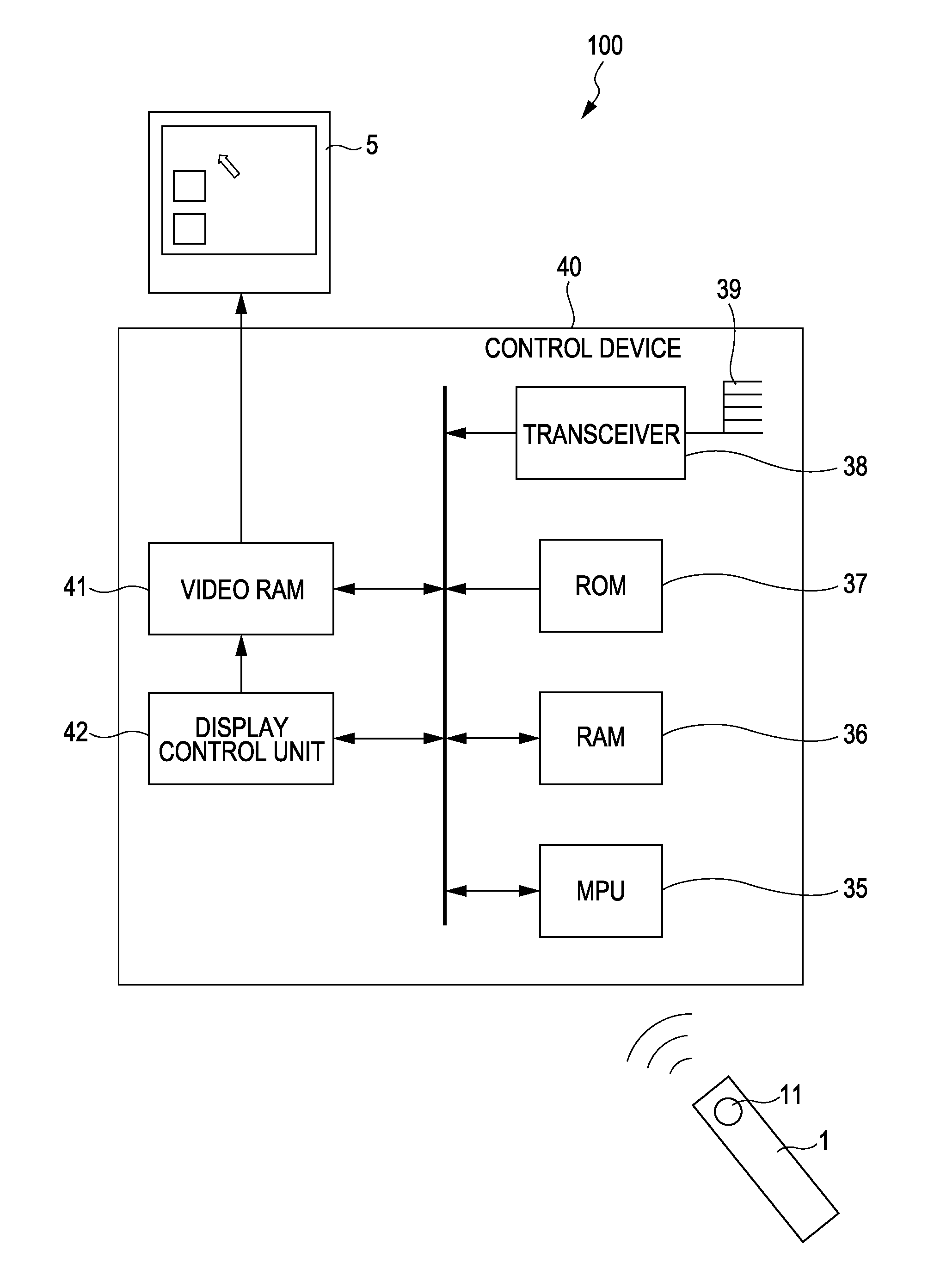
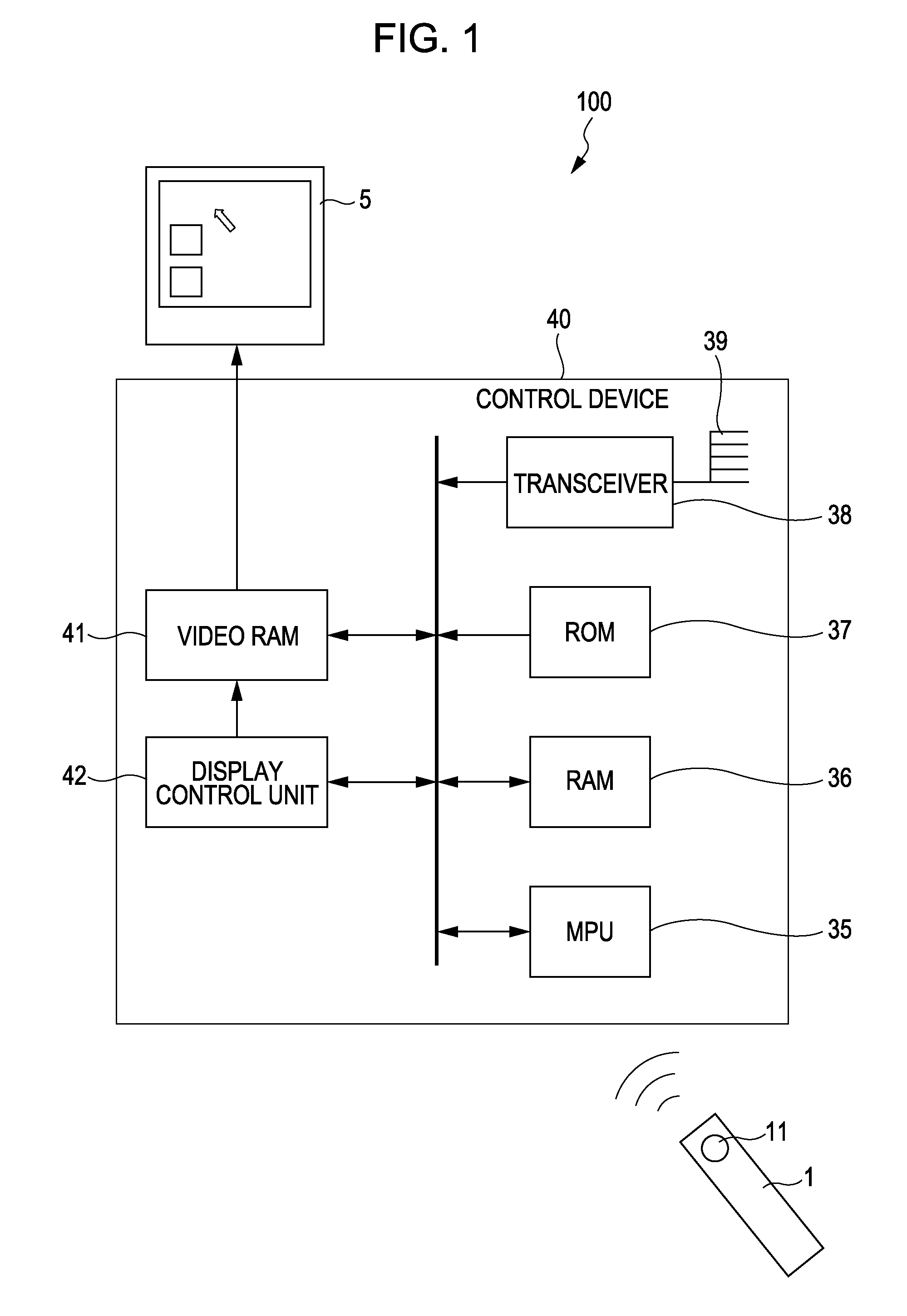
[0236]Next, a control system 100 according to a second embodiment of the present invention will be described. With the second embodiment, description will be made focusing on the operation of the control device 40 included in the control system 100 according to the second embodiment.
[0237]The second embodiment differs from the above first embodiment in that the coordinate values of the virtual pointer 2″ (first coordinate values) are moved to the real screen region 51 not only when the user releases the thumb from above the button 11, but also when a determination command is transmitted from the input device 1. Accordingly, description will be made focusing on this point.
[0238]FIG. 17 is a flowchart illustrating the operation of the control device 40 according to the second embodiment. FIG. 18 is a diagram illustrating an example of the movement of the virtual pointer and real pointer in the case that the processing shown in FIG. 17 has been executed.
[0239]In ST501 through ST509, th...
third embodiment
Modification of Third Embodiment
[0272]In FIGS. 19 and 20, description has been made regarding a case where of the eight divided virtual screen regions 52a through 52h, in the event that the virtual pointer 2″ is positioned on the four corner regions 52b, 52d, 52f, and 52h, the orientation of the real pointer 2′ is constant on each region. However, the display method of the orientation of the real pointer 2′ in the event that the virtual pointer 2″ is positioned on the four corner regions 52b, 52d, 52f, and 52h, is not restricted to this. For example, the orientation of the real pointer 2′ may be changed according to the position of the virtual pointer 2″.
[0273]FIG. 21 is a diagram for describing an example in a case where in the event that the virtual pointer 2″ is positioned on a corner region, the orientation of the real pointer 2′ may be changed according to the position of the virtual pointer 2″. FIG. 21 illustrates, of the four corner regions 52b, 52d, 52f, and 52h, change in t...
PUM
 Abstract
Description
Claims
Application Information