
3D Data Representation, Conveyance, and Use

Inactive Publication Date: 2010-12-09
DIGIMARC CORP
View PDF17 Cites 113 Cited by
  • Summary
  • Abstract
  • Description
  • Claims
  • Application Information

AI Technical Summary

Benefits of technology

[0057]The right eye & left eye images are highly correlated. This means that large groupings of pixels can undergo common shifts, and thus be coded efficiently with a single shift value.
[0067]Beyond the before mentioned benefits, such techniques offer opportunities for customization by the consumer. Similar to the ability to tune the “staging” of the soundtrack of a movie with settings such as “studio” or “hall” etc. in a surround sound receiver, the same could be accomplished for the depth of the video. End users would be afforded the opportunity to scale the depth of the video for their viewing environment, an important factor in enhancing the experience. They could opt for a shallow “stage” or exaggerate the depth to their liking.
[0069]According to one aspect, the present technology involves a system including a receiving device coupled to a source of video data, a display system for presenting rendered video data to a viewer, and a decoder for extracting steganographically encoded 3rd dimension parameters from the video data. The system further includes a control for varying application of extracted 3rd dimension parameters to rendering of the video data by the display system. By such arrangement, the system is able to render the same video data to yield different degrees of 3D effect, based on the control. In one particular arrangement the control is viewer-settable, enabling the viewer to vary the apparent depth of the 3D experience in accordance with the viewer's preference.
[0070]According to a related aspect, the present technology involves a method in which a steganographic encoding apparatus is used to steganographically encode 3rd dimension parameter data into video data. This encoded video data is transmitted to first and second viewing systems. The encoded 3rd parameter data does not define any one particular rendering experience, but rather enables the first viewing system to render the video with a first 3D effect, and enables the second viewing system to render the video with a second, different, 3D effect.

Problems solved by technology

A key challenge raised in migrating 3D video (and to a lesser extent still imagery) out of the Digital Cinema and into the digital living room, is the need to be backwards compatible with existing transport mechanism, protocols and displays.
etc.) to deliver 3D content for the home is problematic, especially if it is not backwards compatible with existing displays and devices.
However, these proposed techniques suffer a variety of drawbacks.

Method used


Image

  • 3D Data Representation, Conveyance, and Use
  • 3D Data Representation, Conveyance, and Use
  • 3D Data Representation, Conveyance, and Use

Examples


Embodiment Construction

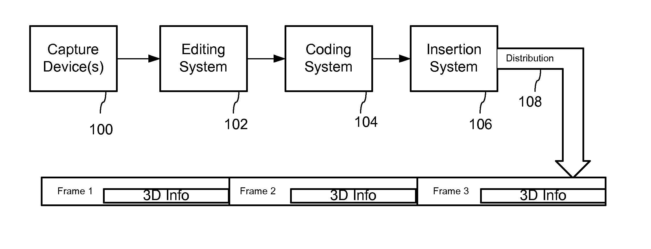
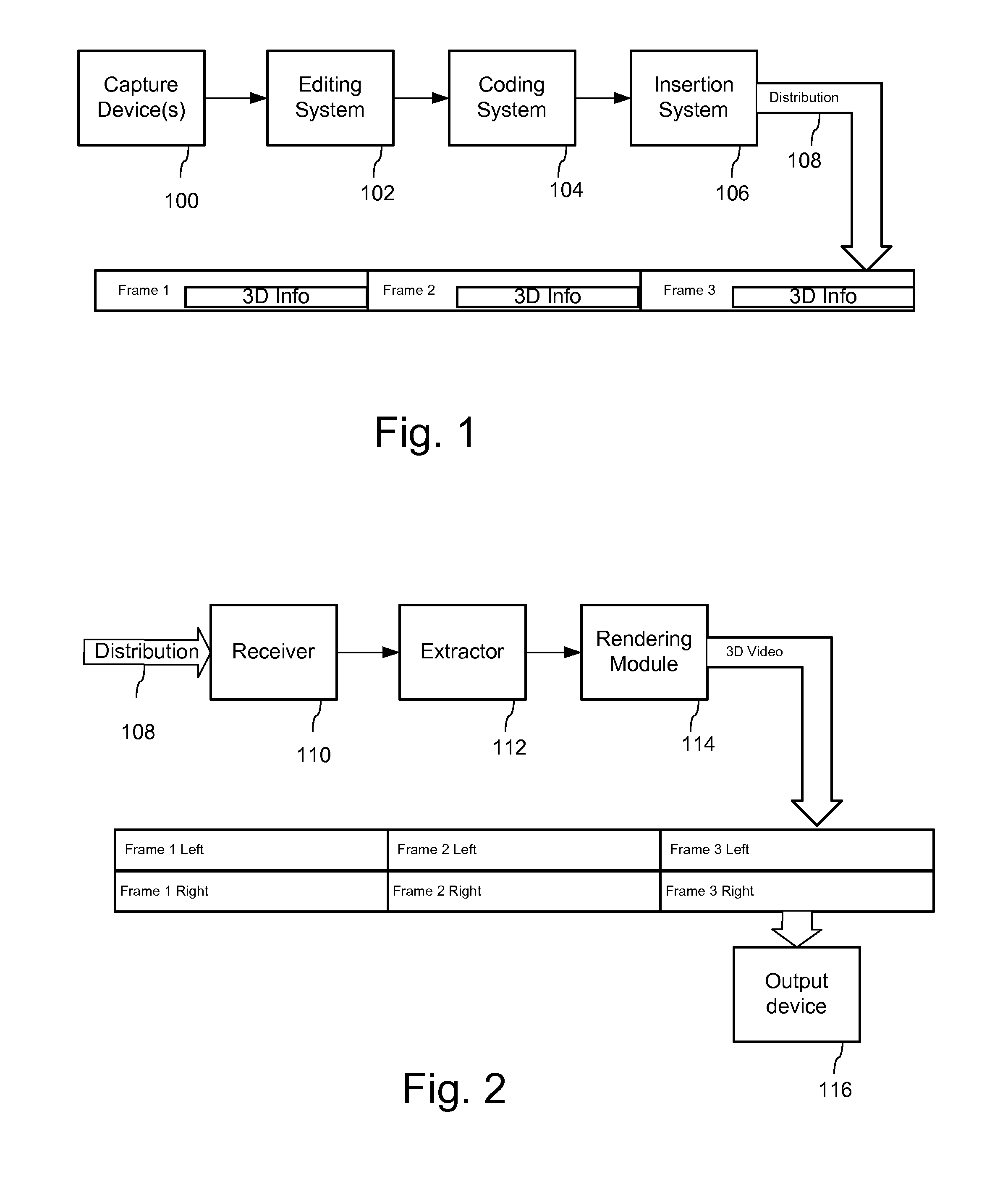
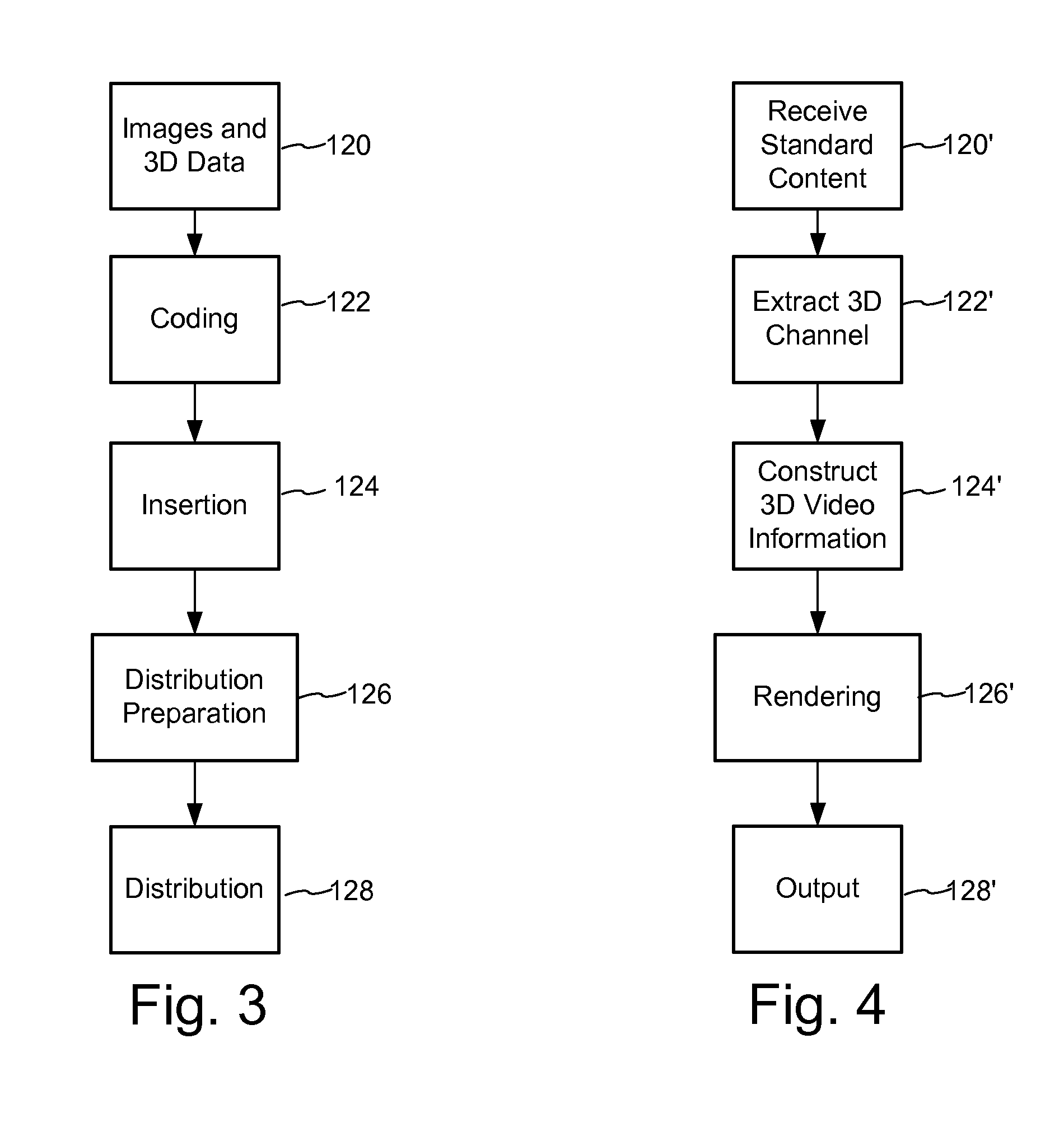
[0024]The following sections describe examples of workflows and systems for creating, coding, transmitting and rendering 3D video. The term 3D video is not intended to be limiting, but instead, is intended to encompass formats for representing image content on a video output device that gives the viewer the perception of three dimensional objects. These include formats for representing stereoscopic video, omni-directional (panoramic) video, interactive, multiple view video (free viewpoint video) and interactive stereo video. These formats also include 3D still imagery, including stereoscopic still images. In addition to the horizontal (X) and vertical (Y) locations corresponding to image sample locations for the 2D display, 3D video equipment used with a 2D display depicts a third dimension, called depth (or disparity), typically represented by the variable, Z. Humans perceive a 3D effect because each eye views the world from a different perspective. Likewise, in the field of stereo...


PUM


Abstract

3D video can be transmitted in a legacy 2D video format by conveying 3rd dimension parameters within a steganographic channel of the perceptual video signal, e.g., DCT coefficients, video samples (luminance, chrominance values), etc. The 3rd dimension parameters can be coded as depth values, disparity, displacement, difference, or parallax values, including depth that is converted into X-Y shifts for adjustment to motion vectors in coded video sequence. To limit the amount of information for the steganographic channel, the 3rd dimension information can be quantized relative to the depth from viewer and other prioritization parameters that limit the need for 3rd dimension information to only aspects of the scene that are deemed important to create a desired 3D effect.

Description

RELATED APPLICATION DATA[0001]This application claims the priority to provisional application 61 / 162,201, filed Mar. 20, 2009, which is incorporated herein by reference.TECHNICAL FIELD[0002]The present disclosure relates to stereoscopy and 3D video, and to related creation, transmission and rendering of 3D video.INTRODUCTION[0003]A key challenge raised in migrating 3D video (and to a lesser extent still imagery) out of the Digital Cinema and into the digital living room, is the need to be backwards compatible with existing transport mechanism, protocols and displays. Put another way, requiring build-out of new distribution channels (infrastructure at cable operators, set-top boxes, DVR's. etc.) to deliver 3D content for the home is problematic, especially if it is not backwards compatible with existing displays and devices. It is the conversion from black & white (BW) to color transmission all over again, except that this time there is much more infrastructure at play, as the distri...

Claims


Application Information

Patent Timeline
IPC IPC(8): H04N13/00
CPCH04N13/0059H04N19/597H04N19/467H04N19/46H04N19/61H04N19/52H04N13/194
Inventor RODRIGUEZ, TONY F.
Owner DIGIMARC CORP
Learn More