Method for Forming Variable Focus Liquid Lenses in a Tubular Housing

a liquid lens and variable focus technology, applied in the field of optical systems, can solve the problems of small optical path modulation, slow and expensive device that relies on manual positioning, and small electro-optic coefficient of tunable gradient index lenses,

Inactive Publication Date: 2010-12-09
AGENCY FOR SCI TECH & RES
View PDF3 Cites 12 Cited by
  • Summary
  • Abstract
  • Description
  • Claims
  • Application Information

AI Technical Summary

Problems solved by technology

However, devices that rely on such manual positioning can be slow and quite expensive.
Tunable gradient index lenses have inherent limitations associated with the relatively small electro-optic coefficients found in the majority of electro-optic materials.
This results in a small optical path modulation and, therefore, requires thick lenses or very high voltages to be employed.
In addition, many electro-optic materials show strong birefringence that causes polarization dependence of the microlens, which distorts light with certain polarization.
However, they require external actuation devices, such as micropumps, to operate.
Integration of such actuation devices into optoelectronic packages involves substantial problems associated with their miniaturization and positioning.
These become especially severe in the case where a two-dimensional array of tunable microlenses is required.
As an example, one weakness of the existing camera phones is that they use tiny, fixed-focus lenses, which have poor light-gathering capabilities, very limited focus range and limited resolution power.
As a result, the image quality is rather low compared to conventional photo cameras.
Most variable focus lenses are limited to lenses actuated using the electro wetting effect (U.S. Pat. No. 6,538,823) and less successfully using liquid crystals.

Method used


Image

  • Method for Forming Variable Focus Liquid Lenses in a Tubular Housing
  • Method for Forming Variable Focus Liquid Lenses in a Tubular Housing
  • Method for Forming Variable Focus Liquid Lenses in a Tubular Housing

Examples


Embodiment Construction

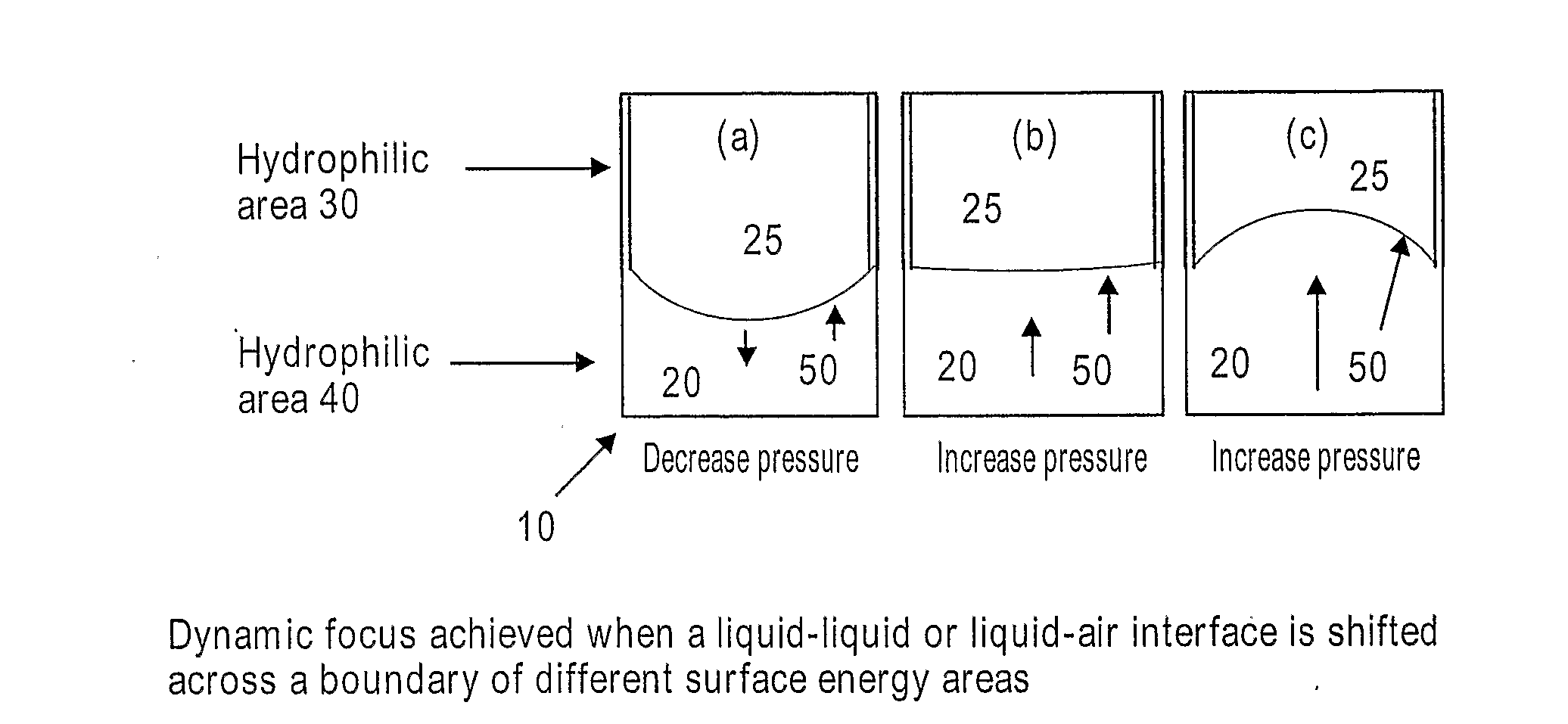
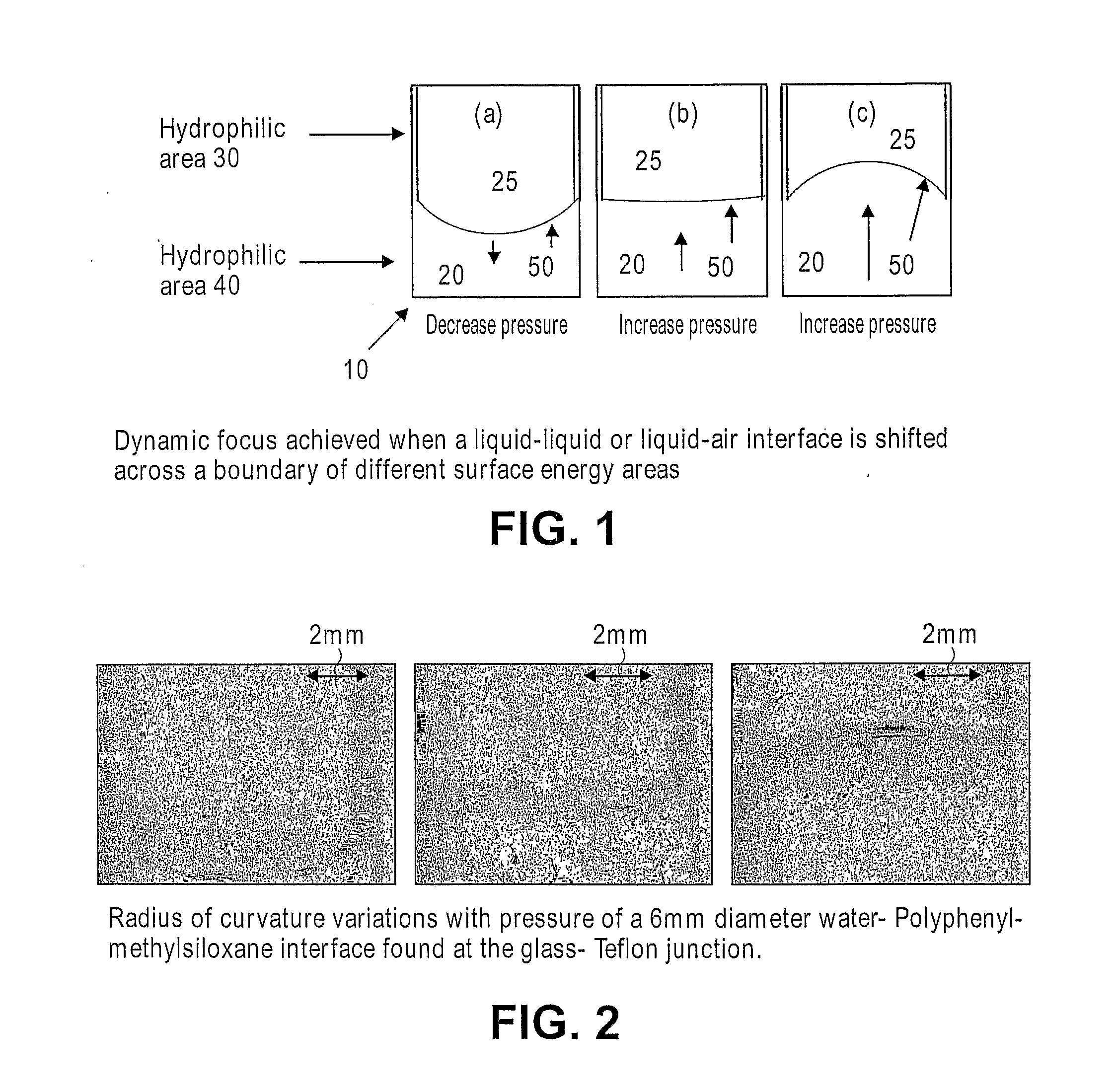
[0024]The present invention provides a variable focus fluid lens wherein the focal length is controllable by changing the contact angle of a fluid meniscus.

[0025]FIG. 1 illustrates an optical device having an adjustable focus fluid lens according to one embodiment of the present invention. As shown, a tubular housing 10 includes a hydrophobic region 30 adjacent a hydrophilic region 40. A first fluid 20, such as water, is contained within tubular housing 10. As shown, the fluid 20 is constrained at the boundary between the hydrophobic region 30 and the hydrophilic region 40 due to the hydrophobic properties of region 30. A second fluid 25 further constrains the fluid 20, and a fluid-fluid interface, or meniscus, 50 is formed. Second fluid 25 may include a gas or a second liquid that is immiscible with the first fluid 20. The contact angle of the fluid-fluid interface 50 defines the curvature of the meniscus 50, which in turn defines the focal length of the fluid lens.

[0026]The schema...


PUM


Abstract

The present invention provides a variable focus fluid lens wherein the focal length is controllable by changing the contact angle of a fluid meniscus. A liquid (20), such as water, is filled in a tubular housing (10) with an internal surface including adjacent hydrophilic (40) and hydrophobic (30) areas or regions, wherein the boundary between the hydrophilic and hydrophobic regions constrains the liquid (20) and presents a meniscus (50) having a curvature defined, in part, by the static contact angle at the boundary. When a control pressure is applied to the liquid (20), the curvature of the meniscus (50) varies as the contact angle of the liquid changes at the boundary.

Description

BACKGROUND OF THE INVENTION[0001]The present invention relates generally to optical systems, and more particularly to variable focus fluid lenses.[0002]Lasers, photoconductors, and other optical components are widely used in many optoelectronic applications such as, for example, optical communications systems and camera devices. Traditionally in such applications, manual positioning and tuning of a lens and its surrounding support structure is required to maintain focus of the image onto a detector and to receive light beams originating from different angular directions relative to the lens. However, devices that rely on such manual positioning can be slow and quite expensive.[0003]To eliminate manual tuning, tunable microlenses were developed to achieve optimal optical coupling between an optical source and an optical signal receiver, such as a photodetector. The microlens acts to focus the optical signal onto its intended destination (e.g., the photodetector). In some cases the re...

Claims


Application Information

Patent Timeline
Patent Type & Authority Applications(United States)
IPC IPC(8): G02B3/12G02B1/06
CPCG02B3/14
Inventor DHARMATILLEKE, SAMANRODRIGUEZ FERNANDEZ, ISABELKHAW, AIK HAU
Owner AGENCY FOR SCI TECH & RES
Why Eureka
Try Eureka