Hydraulic optical focusing-stabilizer

Inactive Publication Date: 2007-08-23
NOKIA CORP
View PDF13 Cites 11 Cited by
  • Summary
  • Abstract
  • Description
  • Claims
  • Application Information

AI Technical Summary

Benefits of technology

[0020] According further still to the second aspect of the invention, the thickness of the liquid along the optical axis may be adjusted to provide the predetermined minimum image quality for facilitating an auto-focus function or a zooming function.

Problems solved by technology

Focusing and stabilization are important issues in electronic imaging devices.

Method used


Image

  • Hydraulic optical focusing-stabilizer
  • Hydraulic optical focusing-stabilizer
  • Hydraulic optical focusing-stabilizer

Examples


Embodiment Construction

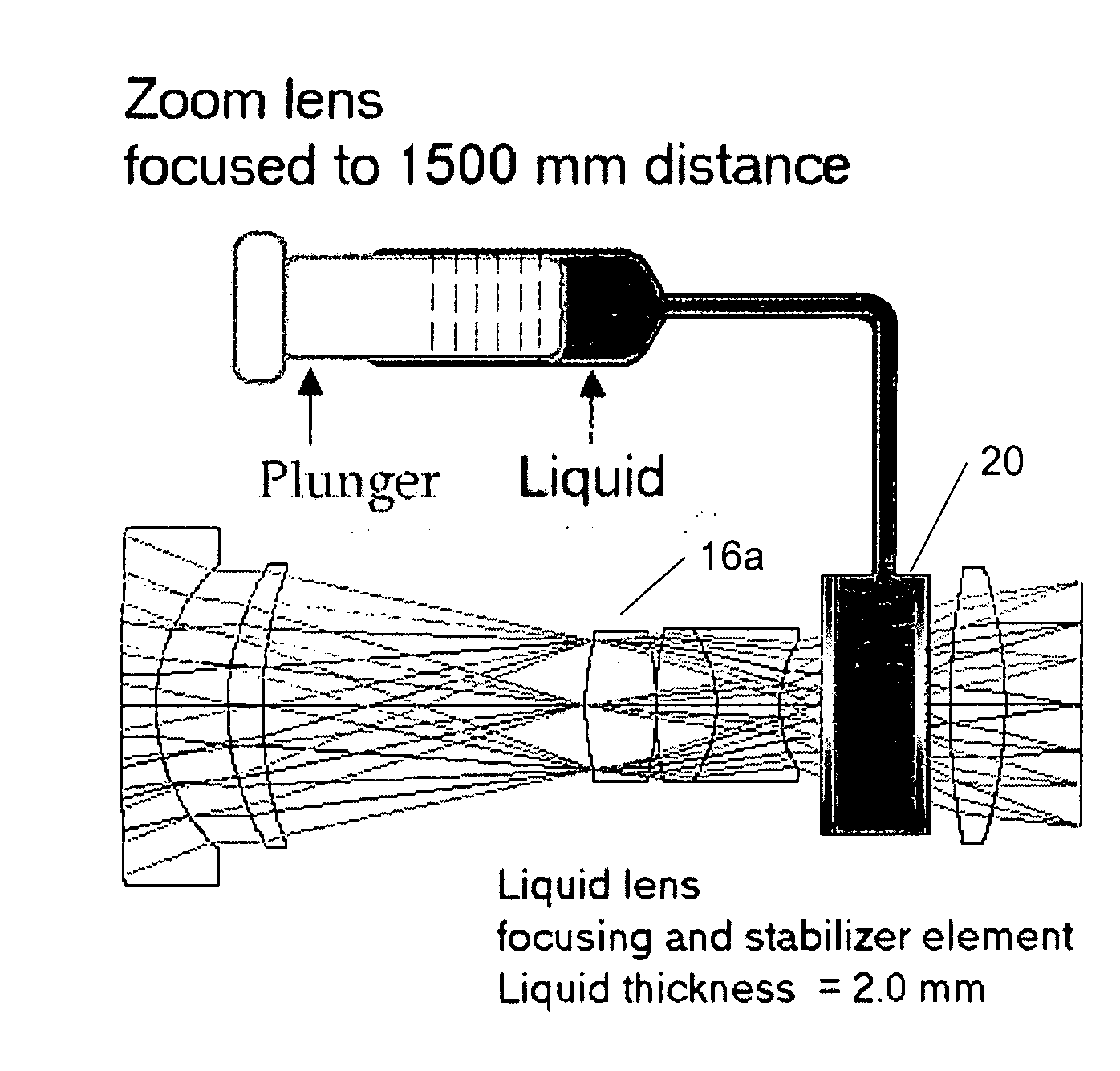
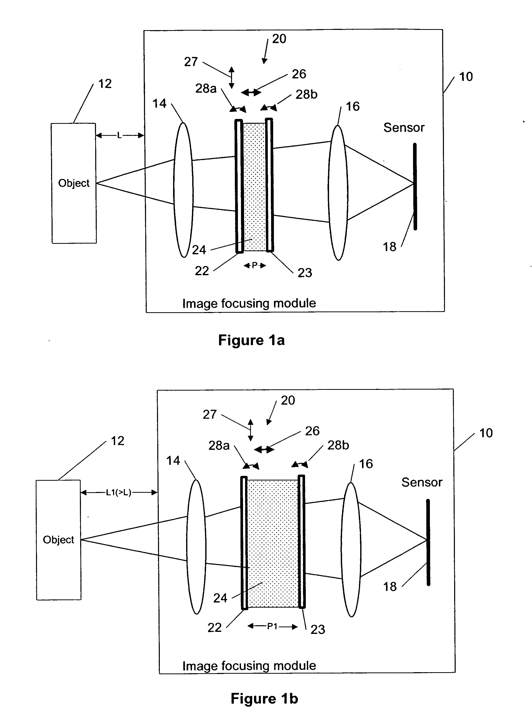
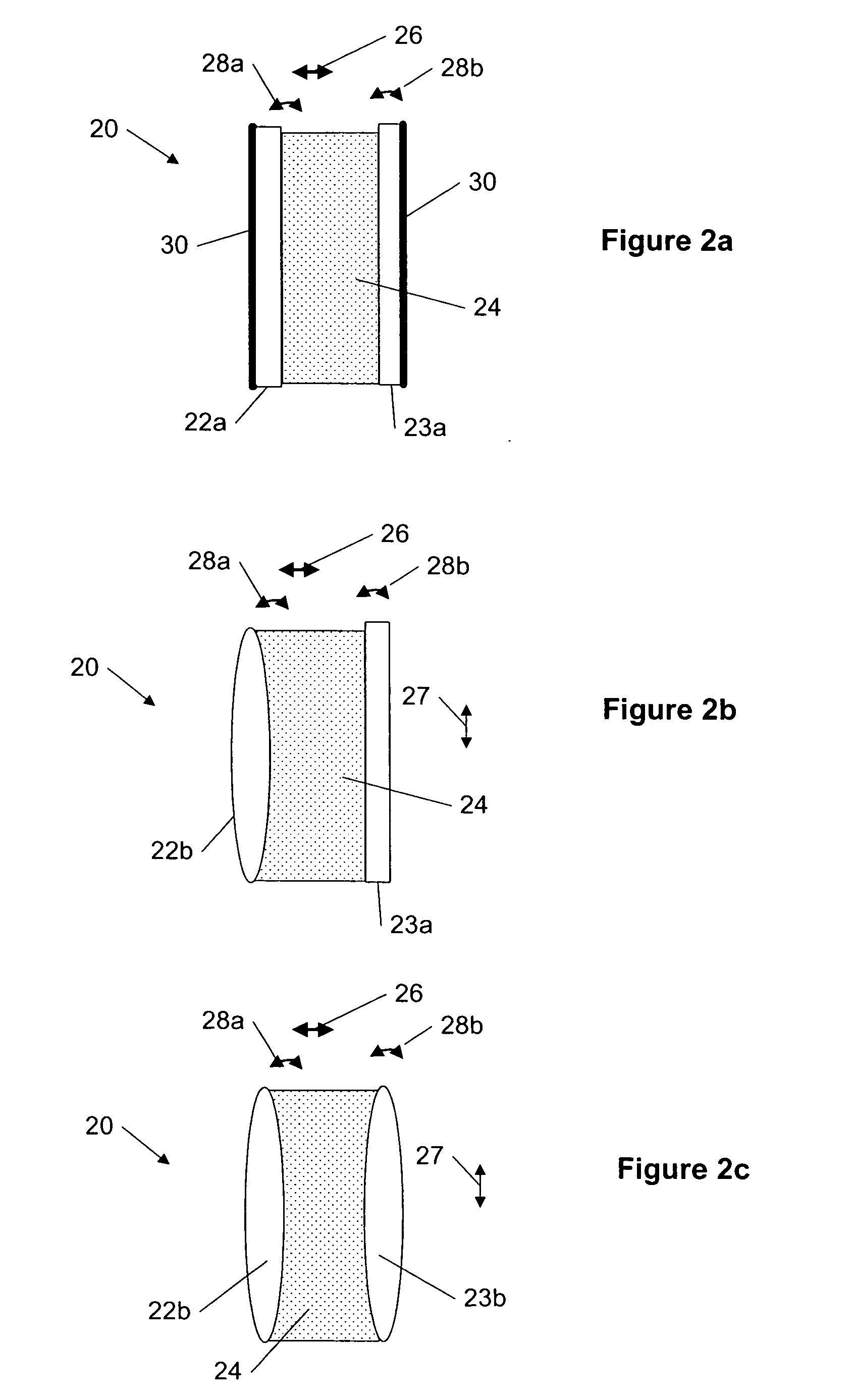
[0030] A new method, apparatus and software product are presented for optical focusing and stabilizing using a hydraulic component in an image focusing module of the electronic devices. According to an embodiment of the present invention, the hydraulic component is a special optical component, a focusing stabilizer, added to optics in the image focusing module. This focusing stabilizer is capable of doing focus adjustment and / or image stabilization. The focusing stabilizer can comprise two optical elements (e.g., two plates or prisms, two lenses, or one plate or prism and one lens) and a liquid between them. If the optical element is located, for example, between an objective lens or a lens group, collecting an optical image of an object, and a photosensitive surface (e.g., a sensor, charge coupled device, photographic paper, etc.), the refractive index (for the liquid refractive index larger than one) and the thickness of the liquid changes a length of the optical path from the obj...


PUM


Abstract

The specification and drawings present a new method, apparatus and software product for optical focusing and stabilizing using a hydraulic component, called focusing stabilizer, in an image focusing module of the electronic devices. This focusing stabilizer is capable of doing focus adjustment and/or image stabilization. The focusing stabilizer can comprise two optical elements (e.g., two plates or prisms, two lenses, or one plate or prism and one lens) and a liquid between them. The refractive index and thickness of the liquid changes a length of the optical path from the object to the photosensitive surface such that the system focus shift depends on a liquid lens thickness in the direction of the optical axis. In addition, adjusting two optical components using a predetermined criterion provides a stabilization of the focused image.

Description

TECHNICAL FIELD [0001] The present invention relates generally to electronic devices and, more specifically, to optical focusing and stabilizing using a hydraulic component in image focusing modules of the electronic devices. BACKGROUND ART [0002] Focusing and stabilization are important issues in electronic imaging devices. Focusing is traditionally done by moving the whole lens back and forth from the sensor or some lens groups in lens systems. More recently a liquid lens focuser system was introduced. [0003] For example, PHILIPS FLUID / FOCUS system mimics the action of the human eye using a fluid lens that alters its focal length by changing its shape. The new lens, which lends itself to high volume manufacturing, overcomes the fixed-focus disadvantages of many of today's low-cost imaging systems. The lens consists of two immiscible (non-mixing) fluids of different refractive index (optical properties), one an electrically conducting aqueous solution and the other an electrically ...

Claims


Application Information

Patent Timeline
Patent Type & Authority Applications(United States)
IPC IPC(8): G02B3/12
CPCG02B1/06G02B3/14G02B27/646G02B26/0891G02B7/102H04N23/60H04N23/55H04N23/686H04N23/6812
Inventor OJALA, KAI MARKUS
Owner NOKIA CORP
Why Eureka
Try Eureka