Mobile communication device, base station device, radio control method, and mobile communication system

a mobile communication and base station technology, applied in the direction of digital transmission, wireless communication, transmission path sub-channel allocation, etc., can solve the problems of rayleigh fading, difficult demodulation process, and greatly deteriorated received signal in the mobile communication device, so as to suppress the deterioration of communication quality and the likelihood of the transmission antenna being switched

Inactive Publication Date: 2010-12-09
SHARP KK
View PDF14 Cites 25 Cited by
  • Summary
  • Abstract
  • Description
  • Claims
  • Application Information

AI Technical Summary

Benefits of technology

[0043]According to the present invention, in the mobile communication device, when the likelihood of the transmission antenna being switched is low, reference signal transmissions from the standby antenna is decreased and the frequency of reference signal transmissions from the transmission antenna is increased. Accordingly, it is possible to optimally perform a process of switching the transmission antenna and to realize proper control (e.g., resource assignment or AMC control) based on the reference signal in the transmission antenna. Realization of such control makes it possible to suppress the deterioration of communication quality.

Problems solved by technology

When a mobile communication device receives a transmission signal from a base station device, a change of a relative position of the base station device and the mobile communication device causes Rayleigh fading.
When the signal amplitude is greatly reduced, a property of the received signal in the mobile communication device is greatly deteriorated, making it difficult to perform a demodulation process.
This increases the size and cost of a mobile communication device.
FIG. 15 shows a problem associated with reference signal transmission described above.

Method used


Image

  • Mobile communication device, base station device, radio control method, and mobile communication system
  • Mobile communication device, base station device, radio control method, and mobile communication system
  • Mobile communication device, base station device, radio control method, and mobile communication system

Examples


first embodiment

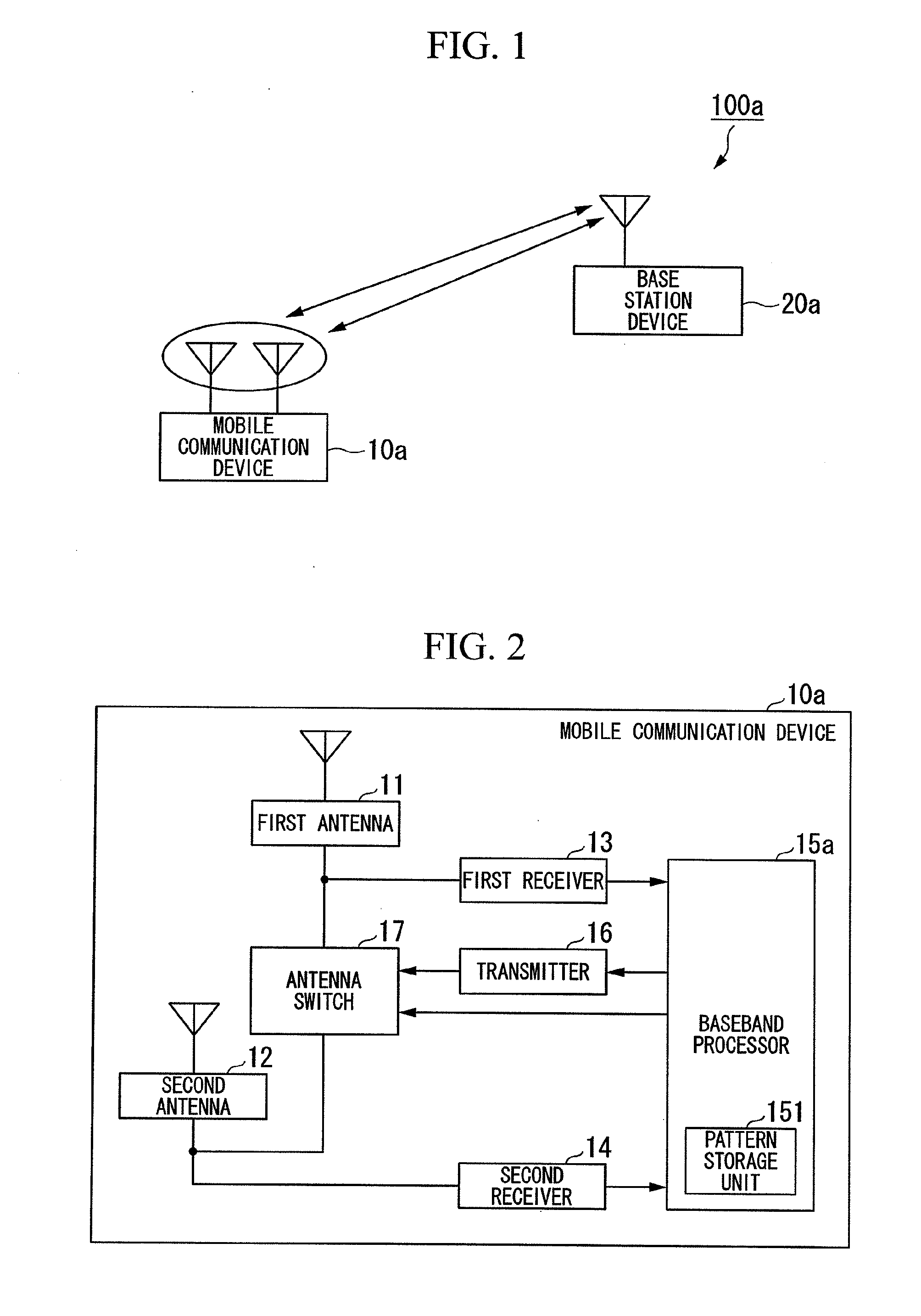
[0060]FIG. 1 shows a network architecture of a mobile communication system 100a (a first embodiment). The mobile communication system 100a includes a mobile communication device 10a including a plurality of antennas, and a base station device 20a. The mobile communication device 10a performs radio communication with the base station device 20a. The mobile communication device 10a performs radio communication with another mobile communication device via the base station device 20a.

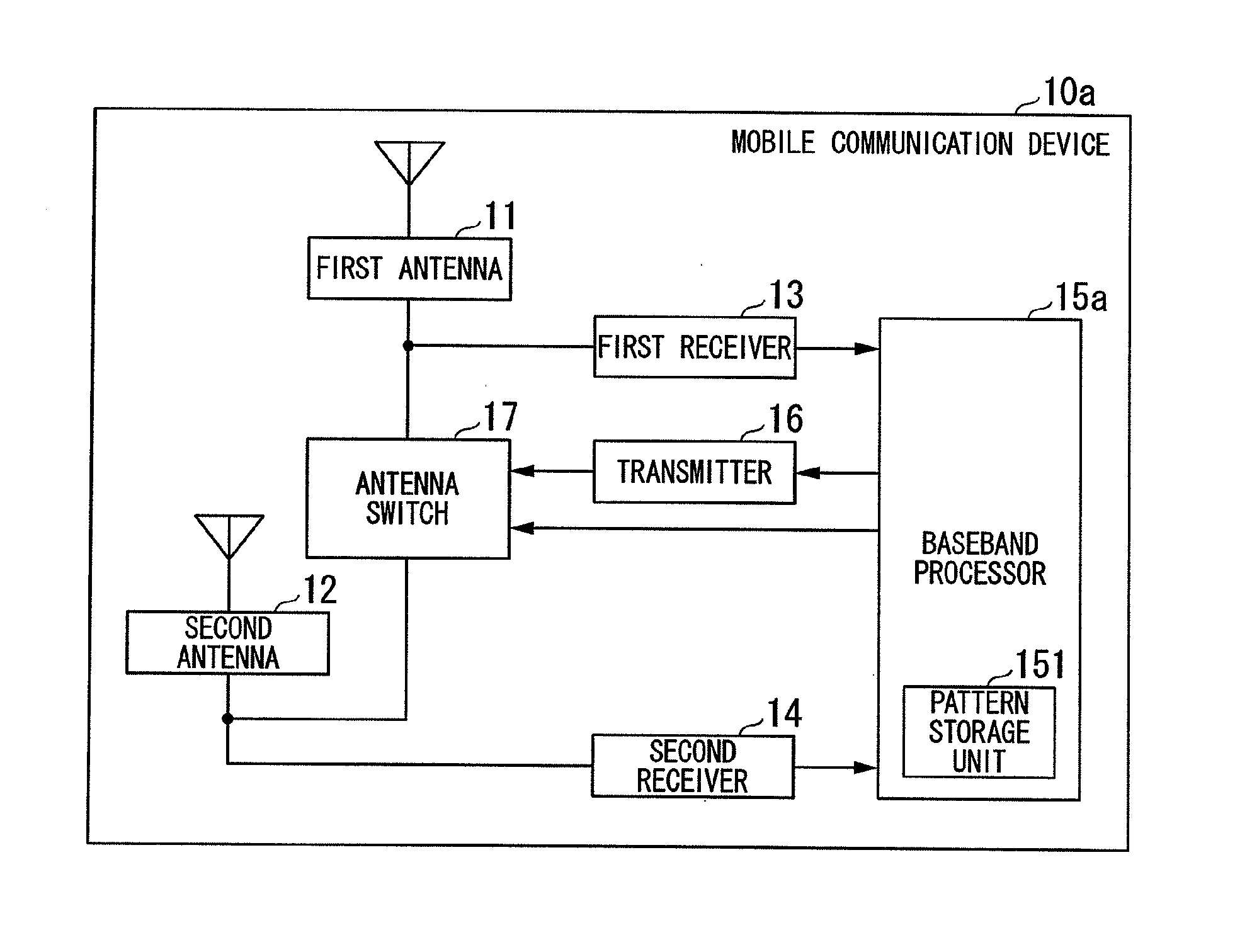
[0061]The mobile communication device 10a includes the plurality of antennas. The mobile communication device 10a transmits reference signals to the base station device 20a using a transmission antenna and a standby antenna. In particular, the reference signal transmitted using the standby antenna is transmitted so that the base station device 20a can determine which antenna is suitable for radio communication with the mobile communication device 10a. The mobile communication device 10a determines a timing...

second embodiment

[0102]In the first embodiment described above, a plurality of patterns are prepared in advance for the reference signal transmissions using the standby antenna, and any one of the plurality of patterns is selected to determine the reference signal transmission timing. On the other hand, in a second embodiment, a determination is made as to whether the reference signal is transmitted from the standby antenna, at predetermined intervals, and a reference signal transmission timing is determined based on the determination. A mobile communication system 100b according to the second embodiment will be described. Since the mobile communication system 100b has the same network architecture as the mobile communication system 100a shown in FIG. 1, a description of the mobile communication system 100b will be omitted.

[0103]The mobile communication system 100b (the second embodiment) includes a mobile communication device 10b and a base station device 20b. The mobile communication device 10b di...

third embodiment

[0121]In the first embodiment described above, the process of transmitting and receiving a signal specific to the control of the timing when the reference signal is transmitted using the standby antenna (e.g., the pattern request signal or the pattern selection signal) is performed each time the first pattern or the second pattern is selected. On the other hand, in a mobile communication system 100c (a third embodiment), a pattern switching trigger is used so that a pattern is switched without causing the transmission and reception of the signal specific to the control of the timing when the reference signal is transmitted using the standby antenna. The mobile communication system 100c according to the third embodiment will be described. Since the mobile communication system 100c has the same network architecture as the mobile communication system 100c shown in FIG. 1, a description of the network architecture of the mobile communication system 100c will be omitted.

[0122]The mobile ...


PUM


Abstract

A mobile communication device includes a plurality of antennas which transmits and receives a radio signal, and a baseband processor which selects a transmission antenna used for data signal transmission from the plurality of antennas based on an instruction from a base station device and transmits a data signal using the transmission antenna, wherein the baseband processor determines a timing when a reference signal is transmitted using a standby antenna not used for data signal transmission based on the likelihood of the transmission antenna being switched and transmits the reference signal based on the determined timing.

Description

TECHNICAL FIELD[0001]The present invention relates to a mobile communication device, a base station device, a radio control method, and a mobile communication system.[0002]This application claims priority to and the benefits of Japanese Patent Application No. 2008-025401 filed on Feb. 5, 2008, the disclosure of which is incorporated herein by reference.BACKGROUND ART[0003]When a mobile communication device receives a transmission signal from a base station device, a change of a relative position of the base station device and the mobile communication device causes Rayleigh fading. The Rayleigh fading greatly changes the phase or amplitude of a received signal. When the signal amplitude is greatly reduced, a property of the received signal in the mobile communication device is greatly deteriorated, making it difficult to perform a demodulation process. Such a phenomenon also occurs even in a reverse link, i.e., when a signal from the mobile communication device is received by the bas...

Claims


Application Information

Patent Timeline
Patent Type & Authority Applications(United States)
IPC IPC(8): H04L27/00
CPCH04B7/061H04B7/0684H04L5/0078H04L5/0023H04L5/0048H04W64/006
Inventor TAKAGI, YUHSUKEHIKOSO, KEIJISAKAMOTO, MITSURUSHIMONABE, TADASHIOHSHIMA, AKIRA
Owner SHARP KK
Why Eureka
Try Eureka