

Signal transmission circuit
a transmission circuit and signal technology, applied in the field of signal transmission circuits, can solve the problems of waveform distortion increase, the inability to adopt a conventional signal transmission circuit, etc., and achieve the effect of reliable communication, low power consumption, and isolation among elements
- Summary
- Abstract
- Description
- Claims
- Application Information
AI Technical Summary
Benefits of technology
Problems solved by technology
Method used
Image

Examples
first embodiment
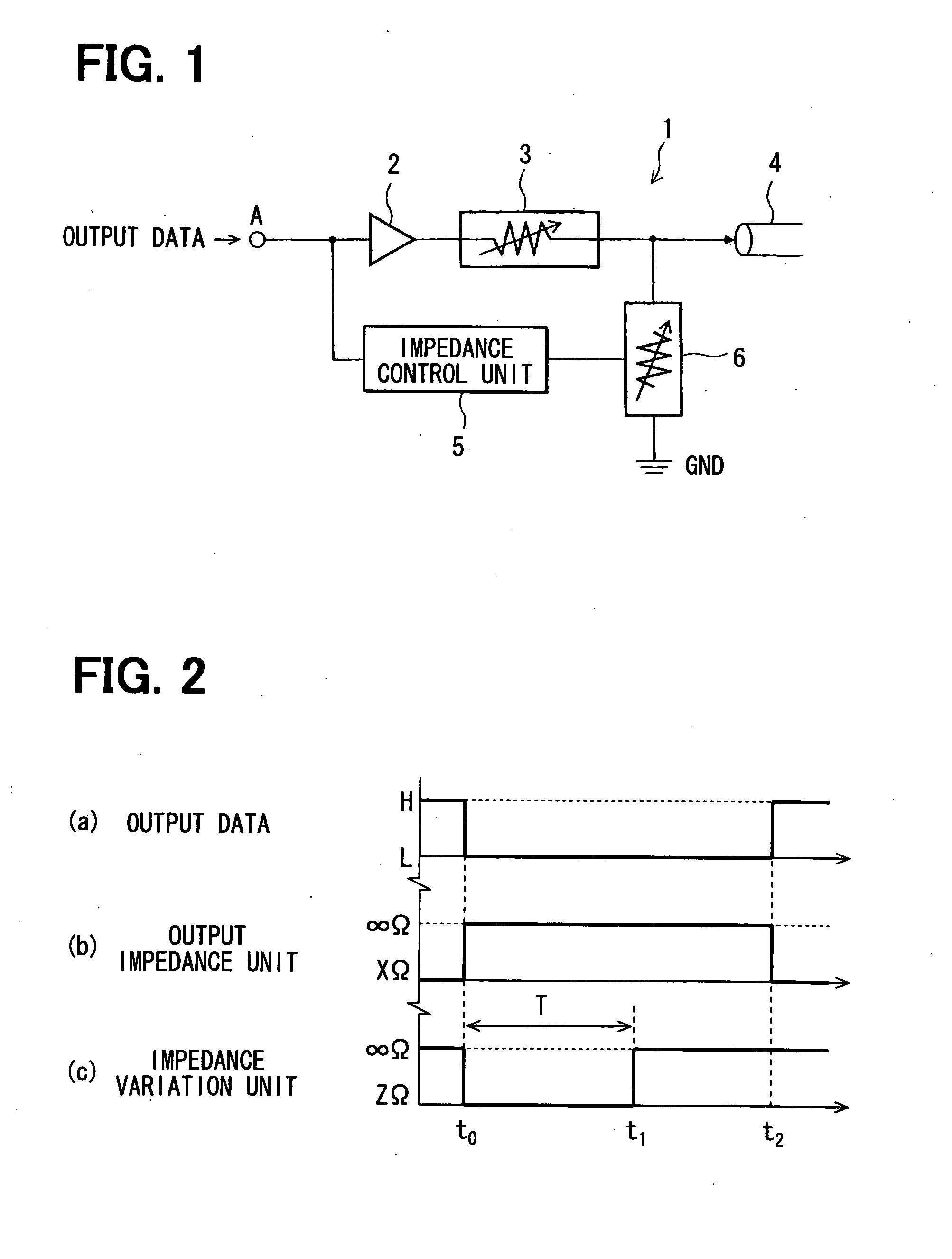
[0045]Referring to FIG. 1 and FIG. 2, a first embodiment will be described below.
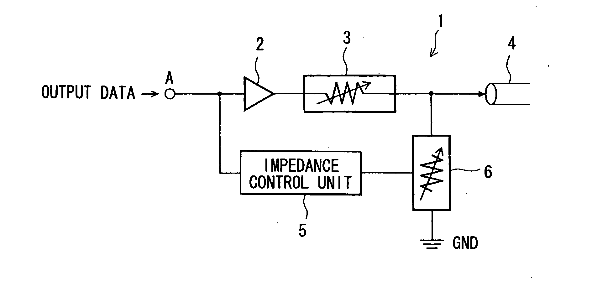
[0046]FIG. 1 shows a signal transmission circuit 1 of the present embodiment. A digital output signal transmitted as data from a signal output circuit (not shown) is applied to a terminal A. The terminal A is connected to an input terminal of an output buffer circuit 2. An output terminal of the output buffer circuit 2 is connected to a signal line 4 via an output impedance unit 3.
[0047]The output impedance unit 3 can be configured such that when a signal input from the output buffer circuit 2 transitions to a high level H, the output impedance unit 3 will set an impedance for the signal line 4 to a predetermined impedance XΩ. When the signal transitions to a low level L, the output impedance unit 3 will set the impedance for the signal line 4 to a high impedance. For example, the output impedance unit 3 enters the equivalent of an open state, presenting an infinite impedance ∞Ω to the signal line 4.
[00...
second embodiment
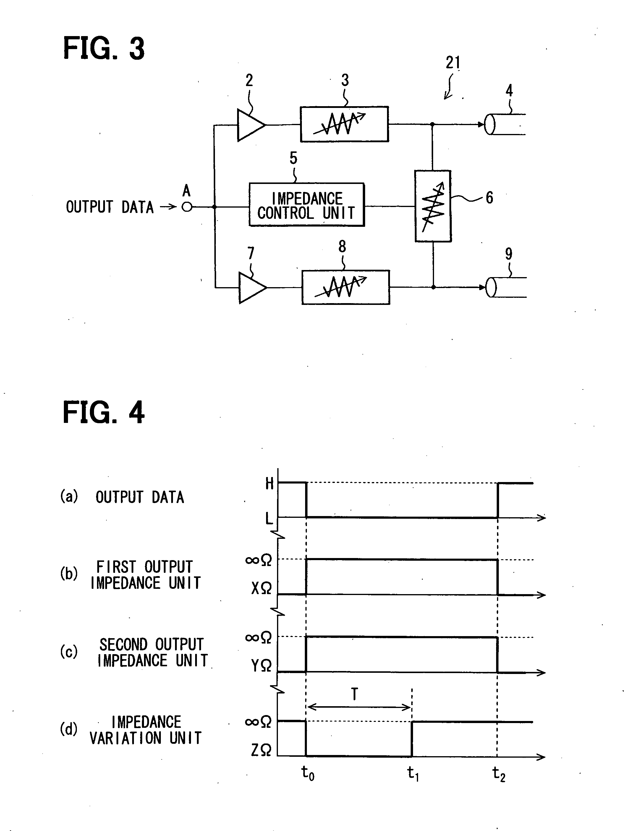
[0057]Referring to FIG. 3 to FIG. 6, a second embodiment is described below. A second embodiment differs from a first embodiment in that, for example, a signal transmission circuit 21 includes two signal lines. The difference from a first embodiment will be described below.
[0058]FIG. 3 shows the circuitry of the signal transmission circuit 21. In addition to the output buffer circuit 2 and output impedance unit 3 included in a first embodiment, an output buffer circuit 7 and an output impedance unit 8 that are identical to the output buffer circuit 2 and output impedance unit 3 respectively are included. In addition to the signal line 4, a signal line 9 is included. The impedance control unit 5 and impedance variation unit 6 are included as they are. The impedance variation unit 6 can vary the terminal impedances in the signal lines 4 and 9.
[0059]The output buffer circuit 2 is equivalent to a first output buffer. The output buffer circuit 2 is configured so that when a signal of a h...
third embodiment
[0069]Referring to FIG. 7, a third embodiment is described below. Herein, a signal transmission circuit 31 includes a concrete example of the impedance variation unit 6 that has been described in relation to a second embodiment. In the present embodiment, the signal transmission circuit 31 is provided with an impedance variation unit 61 including a series circuit composed of an npn bipolar transistor 10 and a resistor 11 presenting an impedance. The resistance of the resistor 11 is set to a value equivalent to the differential impedance between the signal lines 4 and 9. A control signal for controlling the ON and OFF states is input from the impedance control unit 5 to the transistor 10. When the transistor 10 is in the ON state, the resistor 11 terminates the signal lines 4 and 9.
[0070]According to a third embodiment, the same operation and advantage as those of a second embodiment can be provided. In addition, the impedance variation unit 61 can be realized with simple components....
PUM
 Abstract
Description
Claims
Application Information