Variable Rate Diverter For A Crop Residue Collecting Device Carried By A Combine Harvester

Active Publication Date: 2010-12-09
DEERE & CO
19 Cites 17 Cited by

AI-Extracted Technical Summary

Problems solved by technology

While this usage of a wedge-shaped nose for splitting the residue flow worked satisfactorily in respective modes wherein all of the flow was collected or all of the flow was di...

Benefits of technology

[0005]According to the present invention, a combine harvester is equipped with a crop re...

Abstract

A crop residue handling device is mounted to the rear of a combine harvester for intercepting crop residue that remains after grain has been separated from the crop by the separator and cleaning arrangement of the harvester. The residue handling device includes a chopper which chops and impels the chopped residue rearwardly through a discharge duct. A transition duct receives the crop exiting from the chopper and contains upright deflector vanes mounted for pivoting and being automatically moved among desired positions by a power actuator so as to direct desired proportions of the crop residue between a blower for receiving and accelerating the chopped through a discharge chute for collection in a receptacle of a towed trailer, and a pair of spreader disks located at opposite sides of the blower for receiving and dispersing the crop residue on the ground.

Application Domain

Technology Topic

EngineeringCombine harvester +3

Image

  • Variable Rate Diverter For A Crop Residue Collecting Device Carried By A Combine Harvester
  • Variable Rate Diverter For A Crop Residue Collecting Device Carried By A Combine Harvester
  • Variable Rate Diverter For A Crop Residue Collecting Device Carried By A Combine Harvester

Examples

  • Experimental program(1)

Example

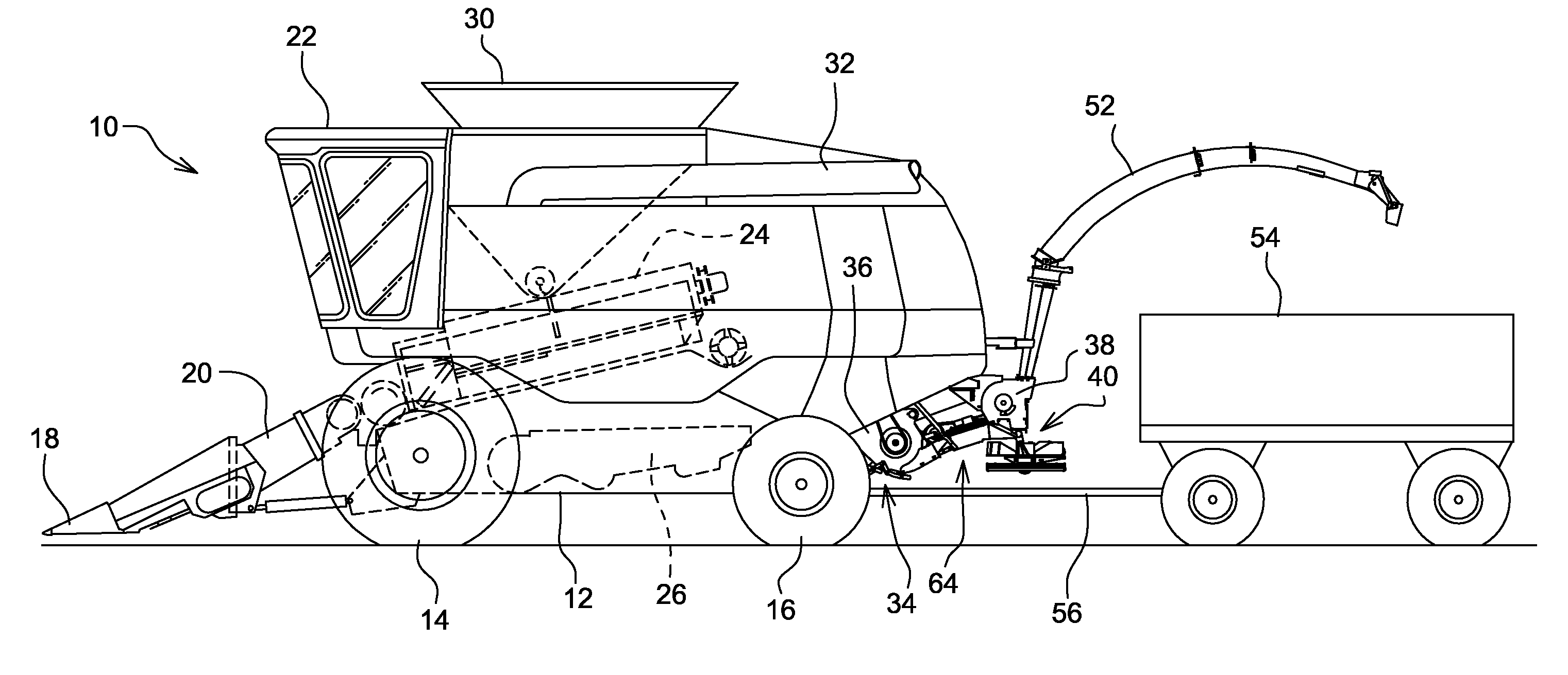
[0013]Referring now to FIG. 1, there is shown a self-propelled combine harvester 10 including a main frame 12 supported on front and rear sets of wheels 14 and 16, respectively. A harvester head 18 is mounted to a feeder house 20 carried at the forward end of the frame 12 so as to be in full view of an operator seated in a cab 22 mounted on the frame 12 above a rear end of the feeder house 20. Stalks or stems of the standing crop being harvested is cut by the harvesting head 18 and conveyed rearwardly, with the attached grain heads or ears, through the feeder house 20 which, in turn, delivers this crop matter to a threshing system 24 located just behind the feeder house and which, in turn, feeds the threshed crop material to a cleaning and separating system 26. Grain that is separated by the system 28 gravitates to the bottom of the system and is conveyed by a grain elevator (not shown) to a holding tank 30 from which the grain can be periodically transferred to a container carried by a grain cart or truck (not shown) by an unloading conveyor 32 when the holding tank 30 becomes full.
[0014]Non-grain crop residue, such as stems, stalks, husks, leaves and cobs is conveyed to the rear from the cleaning and separating system 26. Mounted to the rear of the combine harvester 10 for receiving this crop residue is a crop residue handling arrangement 34 including a rotary chopper 36 for receiving crop directly from the cleaning and separating system 26, and a residue collection blower 38 and a pair of individually driven spreading disks 40 for receiving crop discharged by the chopper 36.
[0015]Specifically, referring now also to FIGS. 2 and 3, it can be seen that the chopper 36 includes a housing 42 including a forward region defining an inlet for receiving crop residue from the cleaning and separating system 28 and guiding it to a blade-carrying rotor 44 having a rear part of its circumference surrounded by a substantially cylindrical housing section, with this housing section having an outlet at a lower rear region thereof that is coupled to, and directs the chopped crop residue into, a discharge duct 46. The crop residue collection blower 38 is provided for the purpose of accelerating chopped crop residue received from the chopper 36. The blower 38 is spaced to the rear from the chopper discharge duct 46 and includes a cylindrical housing 48 encircling a blower rotor 50, including a lower front region defining a crop residue inlet and an upper rear portion defining a crop residue outlet, with the outlet being coupled to an upwardly and rearwardly extending discharge spout 52 having a discharge end oriented for depositing accelerated crop residue into a receptacle of a mobile cart 54 having a wheeled chassis coupled by a tongue 56 for being towed by the combine harvester 10. The pair of crop residue spreader disks 40 are respectively supported on opposite sides of the blower 50 by a support frame 60 suspended from opposite sides of the blower housing 48 by right and left tubular support members with only the left support member 62 being visible (FIG. 2).
[0016]Embodying the present invention and located in the space between the chopper discharge duct 46 and the inlet of blower housing 48 and the two spreader disks 58 is a transition duct 64 including a top wall comprising a central top wall section 66 including a front edge 68 extending the width of the chopper 36 and being fixed to the top of the discharge duct 46. Opposite ends of the front edge 68 are respectively joined to right and left edges 70 and 72 of the central wall section, the edges 70 and 72 converging to a rear edge 74 having the width of the blower housing 48 and being fixed to a top of the blower inlet. Joined to and depending from the top wall section 66 at outer front regions are right and left, rearwardly converging, upright crop deflectors 76 and 78, respectively, each of which includes approximately a forward half which overlaps a bottom extension 80 of the chopper discharge duct 46, with front edges of the deflectors 76 and 78 abutting respective inside surfaces of opposite vertical side walls 82 of the duct 46. A pair of right-angle stiffener members 84 are fixed to the top wall section 66 so as to respectively extend parallel to, and be spaced inwardly from, the side edges 70 and 72 of the top wall section 66.
[0017]Referring now also to FIGS. 4-6, it can be seen that right and left, upright crop residue deflector vanes 86 and 88 are located beneath the central top wall section 66 of the transition duct 64. Each of the deflector vanes 86 and 88 has an upright pivot rod 90 joined to a rear edge thereof and being mounted at opposite ends of the inlet to the blower housing 48 for pivoting about respective upright axis disposed perpendicular to the top wall section 66. The pivot rods 90 project above the top wall section 66, and fixed to each of the rods is one end of an inwardly projecting lever 92. Mounted to the top of the top wall section 66 so as to extend fore-and-aft along a central region of the top wail section 66 is an extensible and retractable electric actuator 94 having a forwardly directed output rod 96 having a forward end region fixed a yoke 98 having opposite ends respectively coupled to inner ends of the levers 86 by a pair of motion-transfer members 100 defined by rods.
[0018]Thus, it will be appreciated that extension and retraction of the actuator 94 will result in the deflector vanes 86 and 88 pivoting about the axes of the pivot rods 90 among various angular positions including a first extreme position wherein forward ends of the deflector vanes 86 and 88 are in engagement with each other, as shown in FIG. 4, wherein all the chopped crop residue exiting the chopper 36 is blocked from entering the crop collection blower 38, and a second extreme position wherein the forward ends of the deflector vanes 86 and 88 are respectively located slightly outwardly of rear ends of the crop deflectors 76 and 78 and direct all of the chopped crop residue exiting the chopper 36 to the collection blower 38.
[0019]Referring back to FIGS. 2 and 3, it can be seen that the transition duct 64 further includes right and left top wall sections 102 and 104, respectively, having inner edges fixed to the outer edges 70 and 72 of the central top wall section 66 and respectively having outer fore-and-aft extending edges spaced apart a distance only slightly less than a width of said chopper 36 and being joined to respective side walls 106 and 108, which are inclined slightly outwardly form top to bottom. The top wall sections 102 and 104 respectively include respective rear regions 110 and 112 that extend beside the blower housing 48 and above inner front quarter regions of the spreader disks 40, as viewed in FIG. 3, with these top wall section being inclined downwardly toward the rear. Provided about an inner rear quarter region of each of the spreader disks 40 is a curved upright baffle 114 that prevents chopped crop residue from passing rearwardly beyond the spreader disks.
[0020]In a manner taught by the aforementioned U.S. Patent Application Publication No. 2008/0248843, the linear electric motor 94 is automatically controlled so as to vary the amount of chopped crop residue passing to each of the collecting blower 38 and the pair of spreader disks 40 in accordance with various soil, crop and terrain parameters, which are sensed on the go and/or are provided by geo-referenced field maps that have been previously generated and placed into the memory of an electronic control unit.
[0021]Having described the preferred embodiment, it will become apparent that various modifications can be made without departing from the scope of the invention as defined in the accompanying claims.

PUM

no PUM

Description & Claims & Application Information

We can also present the details of the Description, Claims and Application information to help users get a comprehensive understanding of the technical details of the patent, such as background art, summary of invention, brief description of drawings, description of embodiments, and other original content. On the other hand, users can also determine the specific scope of protection of the technology through the list of claims; as well as understand the changes in the life cycle of the technology with the presentation of the patent timeline. Login to view more.

Similar technology patents

Method for shipboard operation of electromagnetic gun and rotating pulse forming network

InactiveUS20050016373A1Improve arrangementElectromagnetic launchersWeapon assembly/disassemblyPulse energyEngineering
Owner:GENERAL ATOMICS

Display device

ActiveUS20170090261A1Improve arrangementRetention time be decreaseNon-linear opticsRADIUSLiquid crystal
Owner:INNOLUX CORP

Arrangement for Detecting a Position of a Plunger

ActiveUS20180147350A1Improve arrangementAutomatic syringesMedical devicesBungEngineering
Owner:SANOFI AVENTIS DEUTSCHLAND GMBH

Classification and recommendation of technical efficacy words

  • Improve arrangement

Antenna arrangement for an electronic device and an electronic device including same

InactiveUS7215600B1Improve signal transmission and reception functionalityImprove arrangementTime indicationAntenna supports/mountingsElectricityElectromagnetic radiation
Owner:TIMEX GROUP

Golf ball dimple arrangement method

ActiveUS20050032590A1Improve arrangementImproves such pointGolf ballsSolid ballsCHEEK DIMPLESEngineering
Owner:BRIDGESTONE SPORTS
Why Eureka
Try Eureka