
Apparatus for a needle director for an ultrasound transducer probe

a technology of ultrasound transducer and apparatus, which is applied in the field of medical equipment, can solve the problems of time-consuming, complicated devices, and limited clinical application of these devices

Inactive Publication Date: 2010-12-09
GUAN ZHONGHUI
View PDF27 Cites 69 Cited by
  • Summary
  • Abstract
  • Description
  • Claims
  • Application Information

AI Technical Summary

Benefits of technology

"The invention is an apparatus for a needle director for an ultrasound transducer probe. The apparatus includes an adapter for joining to the ultrasound transducer probe, a needle holder for holding the needle, and a plate for guiding the needle. The apparatus allows for needle insertion in a specific direction and at a specific distance from the ultrasound transducer probe. The apparatus also includes a sterile field for maintaining a clean environment during use. The technical effects of the invention include improved accuracy in needle insertion and reduced risk of complications during ultrasound-guided procedures."

Problems solved by technology

It requires a lot of clinical training and high skill to coordinate both hands to keep the entire needle and the target in the central plane of the transducer probe simultaneously, and it can be very time consuming.
Most of these devices have complicated components, and the majority of these devices have fixed insertion angles.
As a result, the clinical application of these devices has been greatly limited.
However, the devices with a multi-joint arm are too cumbersome for clinical use.
For devices with a slot, it is usually very difficult to insert needles of different sizes through the single size of the slot, and therefore it is very difficult to make one such device that fits all needles.
The partial visualization of the needle often gives the physician a false judgment about the location of the needle tip, which can be dangerous because the unseen needle tip can damage other tissue.
However, so far there is no device that can estimate the needle tip location other than direct visualization by ultrasound.
In other words, if the needle tip is not directly in the central plane, it will not be visualized, and there is no way to know the exact location of the needle tip.
Without knowing the exact location of the needle tip, the ultrasound-guided procedure can be dangerous and ineffective.
In general, the “off plane” technique is considered to be associated with higher risks.
So far there is no existing device that can help to locate the needle tip with the “off plane” technique.
Another problem of ultrasound-guided procedures is that, with both the “in plane” and the “off plane” techniques, there is no current solution for a physician to choose an accurate needle insertion direction beforehand.
This practice, however, greatly increases the risk of the procedure and the discomfort of the patient because the needle is inserted and redirected multiple times within patient's body before it reaches its final direction.
It also significantly prolongs the procedure because a lot of time is consumed in finding the right insertion direction.
With the “off plane” technique, the situation is worse because the needle tip is not be visualized until it reaches the central plane.
As a result, it is often very difficult to know if the needle is heading toward the target before the needle is blindly inserted quite deep into the patient.
Therefore for the “off plane” technique to be safely applied, a device is badly needed to determine the needle insertion direction before the needle is inserted into the patient.

Method used


Image

  • Apparatus for a needle director for an ultrasound transducer probe
  • Apparatus for a needle director for an ultrasound transducer probe
  • Apparatus for a needle director for an ultrasound transducer probe

Examples


Embodiment Construction

[0024]The present invention is best understood by reference to the detailed figures and description set forth herein.

[0025]Embodiments of the invention are discussed below with reference to the Figures. However, those skilled in the art will readily appreciate that the detailed description given herein with respect to these figures is for explanatory purposes as the invention extends beyond these limited embodiments. For example, it should be appreciated that those skilled in the art will, in light of the teachings of the present invention, recognize a multiplicity of alternate and suitable approaches, depending upon the needs of the particular application, to implement the functionality of any given detail described herein, beyond the particular implementation choices in the following embodiments described and shown. That is, there are numerous modifications and variations of the invention that are too numerous to be listed but that all fit within the scope of the invention. Also, ...


PUM


Abstract

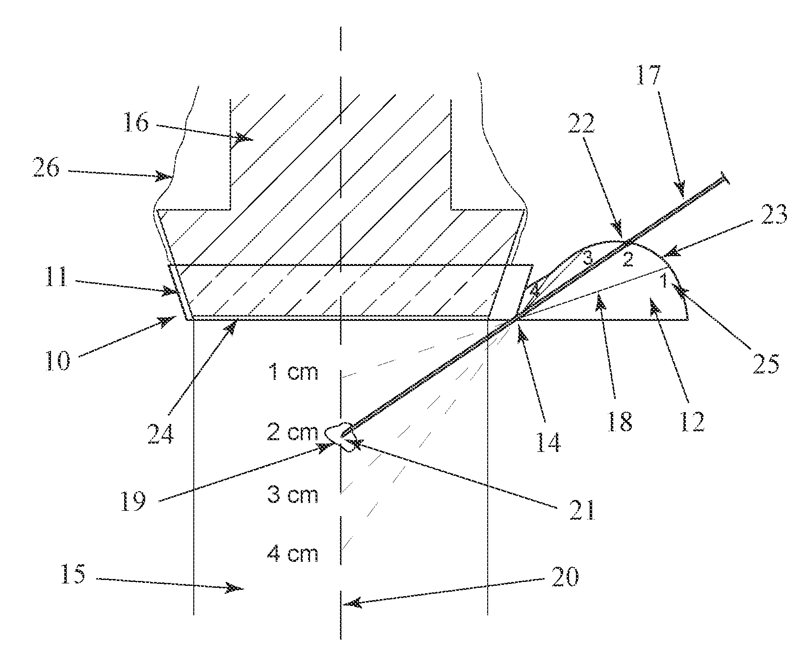
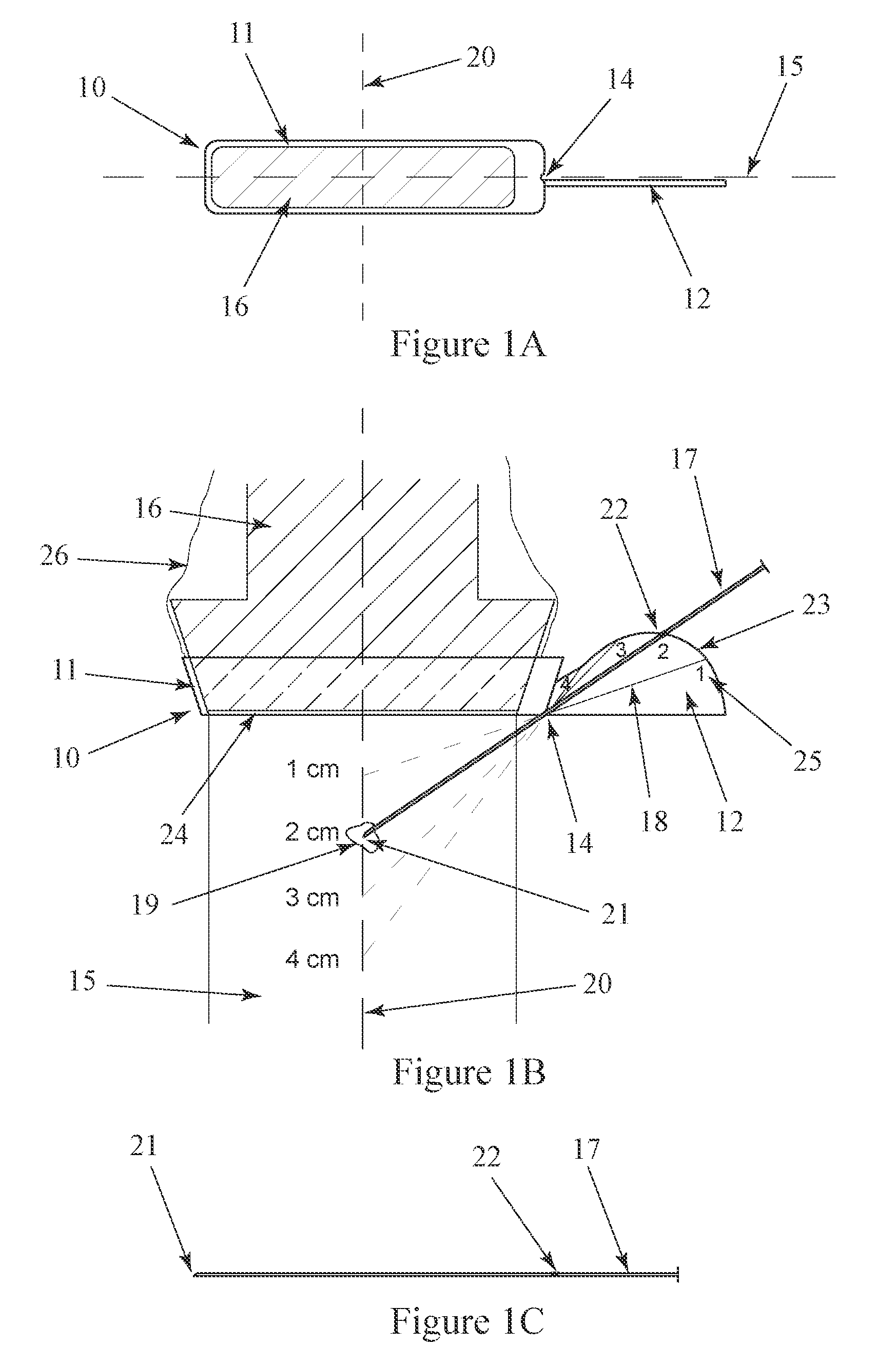
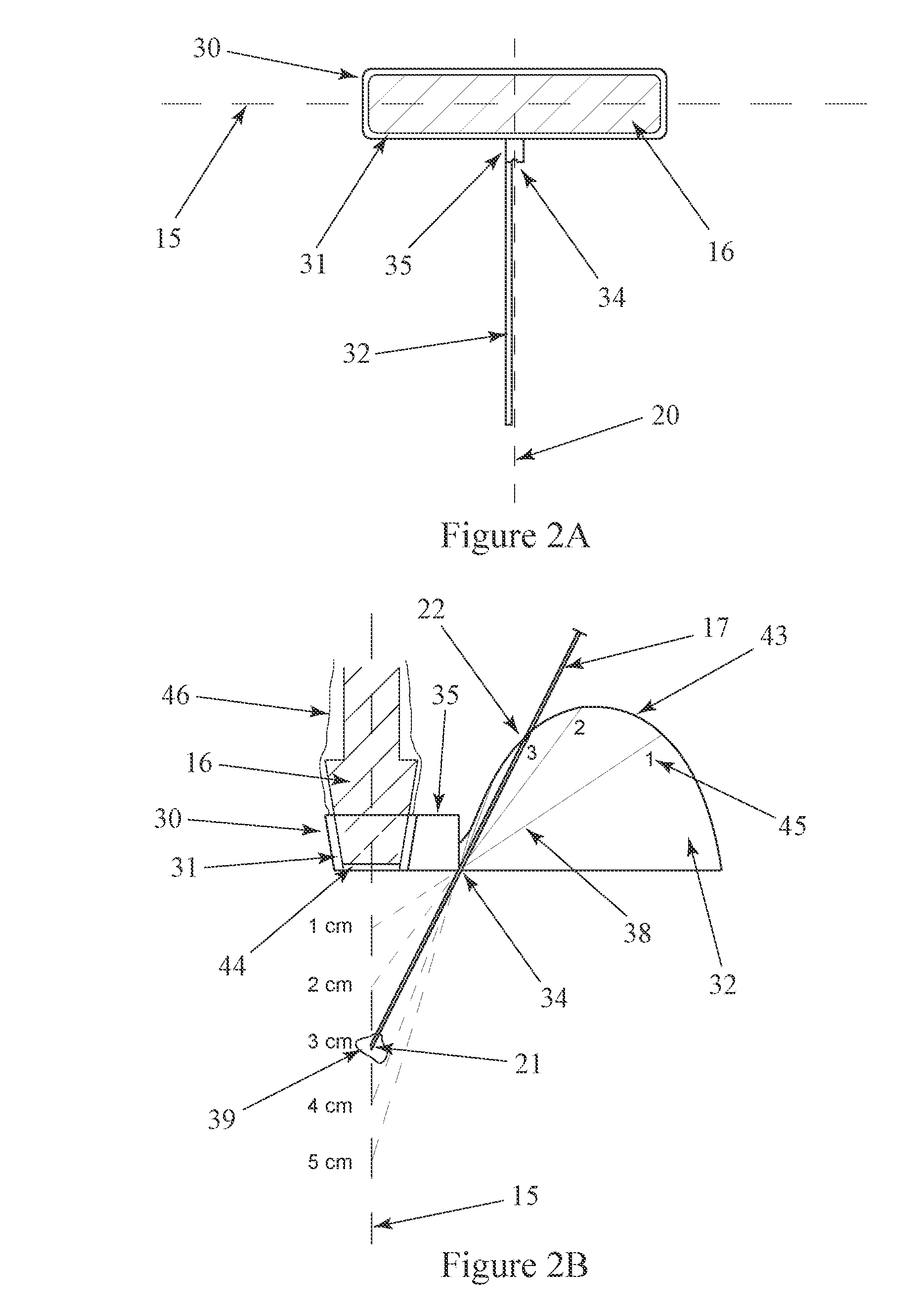
An apparatus for a needle director for an ultrasound transducer probe includes an adapter for joining to the probe. The adapter includes a bottom residing in a first plane perpendicular to a midline of the central plane of the ultrasound transducer probe. A needle insertion site is disposed in the first plane for allowing the needle to pass below the first plane. A plate is disposed in a second plane parallel to and offset from a third plane containing the midline and the needle insertion site. The plate has a flat surface proximate the third plane for guiding an insertion of the needle along the third plane. The flat surface has a plurality of radial lines having indicators of distances along the midline and a curved line intersecting the plurality of radial lines for aligning with a marker on the needle to indicate that a tip of an inserted needle has intersected the midline.

Description

FEDERALLY SPONSORED RESEARCH OR DEVELOPMENT[0001]Not applicable.REFERENCE TO SEQUENCE LISTING, A TABLE, OR A COMPUTER LISTING APPENDIX[0002]Not applicable.COPYRIGHT NOTICE[0003]A portion of the disclosure of this patent document contains material that is subject to copyright protection. The copyright owner has no objection to the facsimile reproduction by anyone of the patent document or patent disclosure as it appears in the Patent and Trademark Office, patent file or records, but otherwise reserves all copyright rights whatsoever.FIELD OF THE INVENTION[0004]The present invention relates generally to medical equipment. More particularly, the invention relates to needle directors for ultrasound-guided procedures.BACKGROUND OF THE INVENTION[0005]Ultrasound is widely used in medical practice. It provides two-dimensional images of the inside structures of human bodies. With the help of ultrasound images, physicians can insert needles into human bodies to reach specific places for many ...

Claims


Application Information

Patent Timeline
Patent Type & Authority Applications(United States)
IPC IPC(8): A61B8/00
CPCA61B8/0833
Inventor GUAN, ZHONGHUI
Owner GUAN ZHONGHUI
Learn More