
Multithread execution device and method for executing multiple threads

a multi-thread execution and thread technology, applied in the direction of program control, computation using denominational number representation, instruments, etc., can solve the problems of inability to obtain desired instruction issue rate, inability to guarantee execution timing of the plurality of programs #b>0/b> and #b>1/b> before integration, and the number of instructions executed per unit time varies

Active Publication Date: 2010-12-09
RENESAS ELECTRONICS CORP +1
View PDF2 Cites 39 Cited by
  • Summary
  • Abstract
  • Description
  • Claims
  • Application Information

AI Technical Summary

Benefits of technology

[0020]The present invention provides a multithread execution device and a method of executing multiple threads that can dynamically optimize the number of instructions executed per unit time by a CPU.
[0023]The present invention can provide the multithread execution device and the method for executing multiple threads that can dynamically optimize the number of instructions executed per unit time by a CPU.

Problems solved by technology

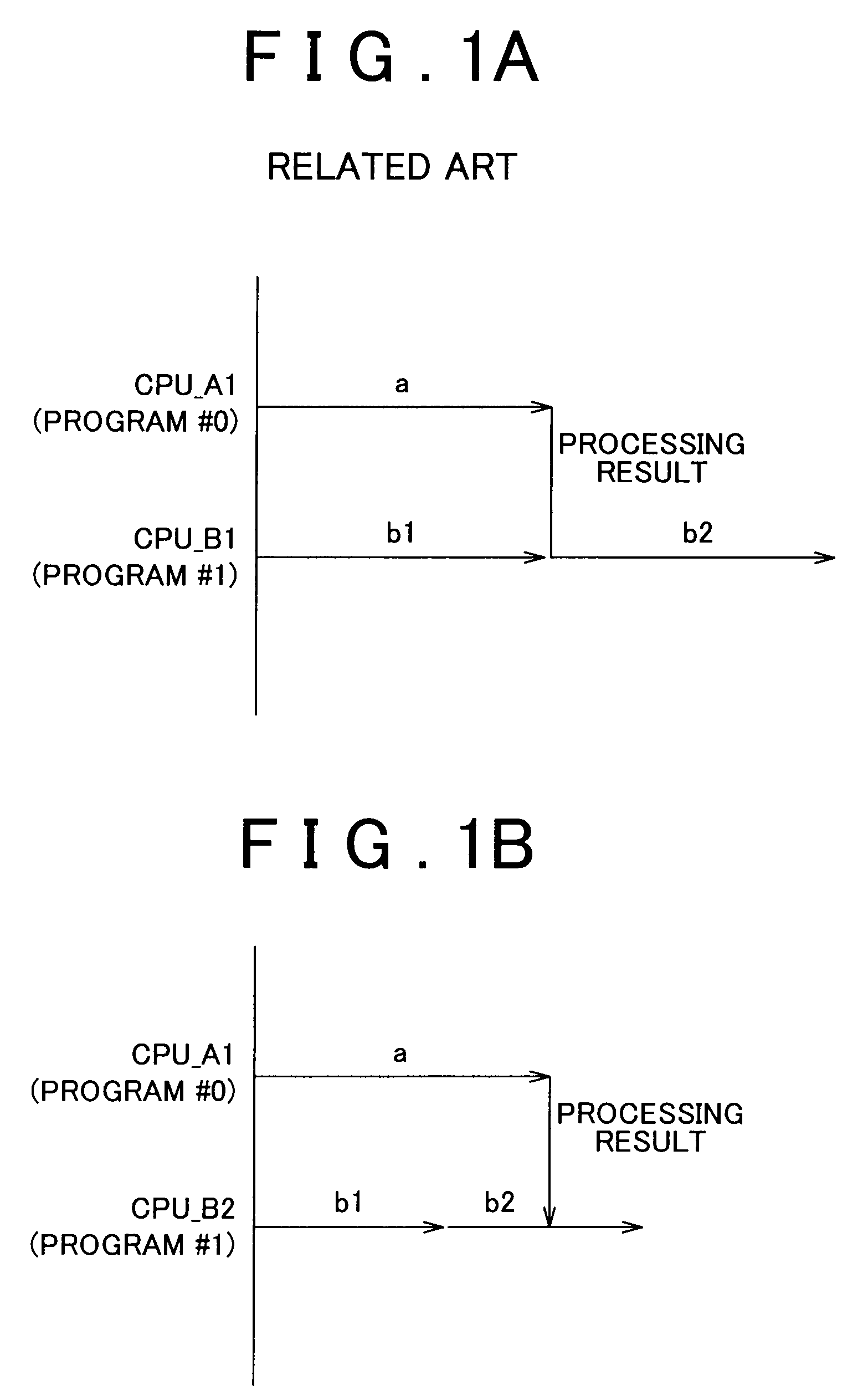
Thus, the same problem as that in FIG. 1B occurs if the program #0 and the program #1 that exhibit dependency to each other are simply ported to the integrated ECU.
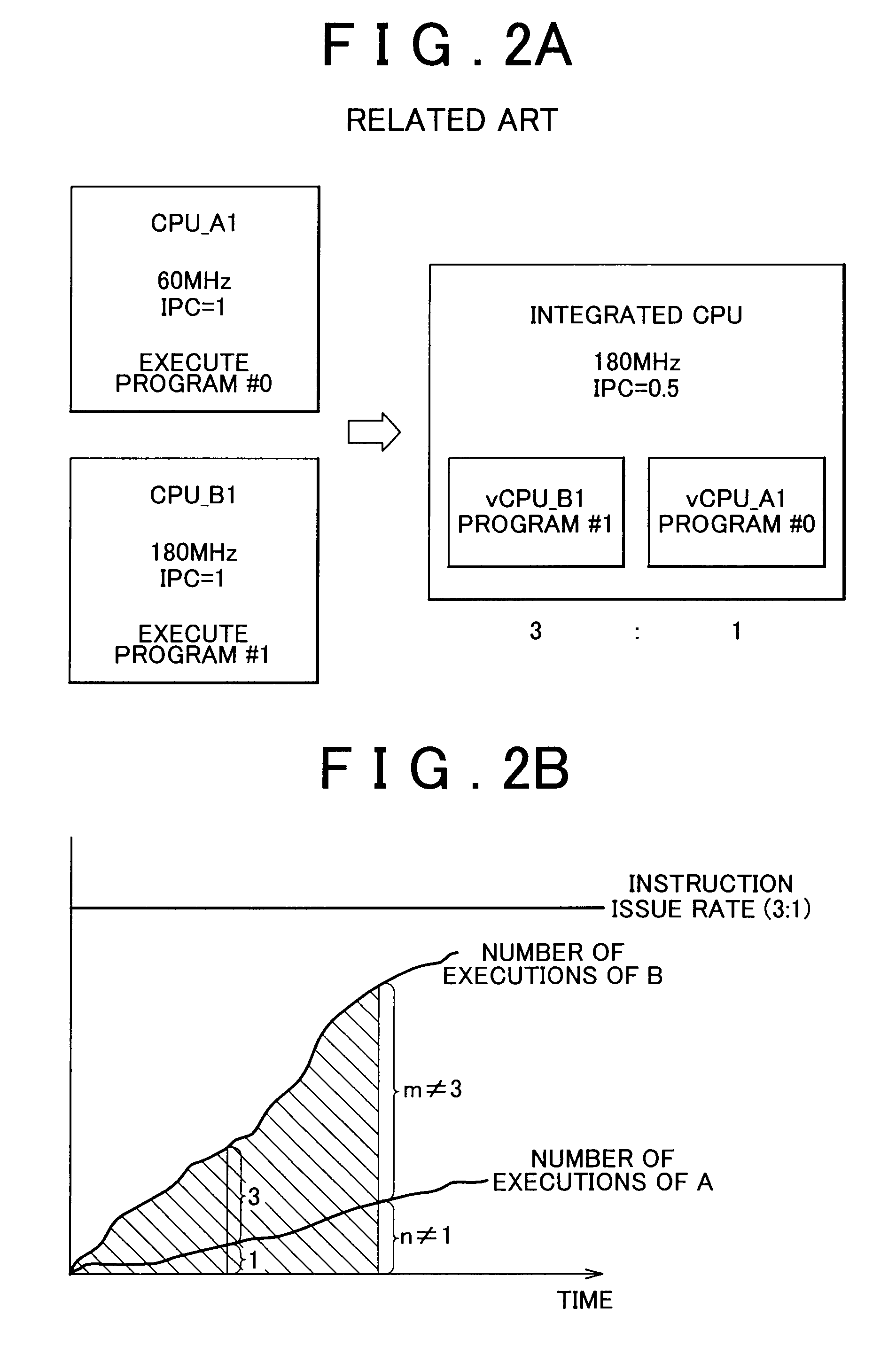
In addition, when the integrated CPU includes a pipeline with multiple steps or includes a plurality of pipelines, the number of instructions executed per unit time varies due to a hazard or a stall.
Thus, even when the instruction issue rate is determined in consideration of the IPC, a desired instruction issue rate cannot be obtained.
More specifically, when the plurality of programs #0 and #1 are integrated by using the multithreading technology or the multi-core in the related art, the execution timings of the plurality of programs #0 and #1 before integration cannot be guaranteed after integration.

Method used


Image

  • Multithread execution device and method for executing multiple threads
  • Multithread execution device and method for executing multiple threads
  • Multithread execution device and method for executing multiple threads

Examples


Embodiment Construction

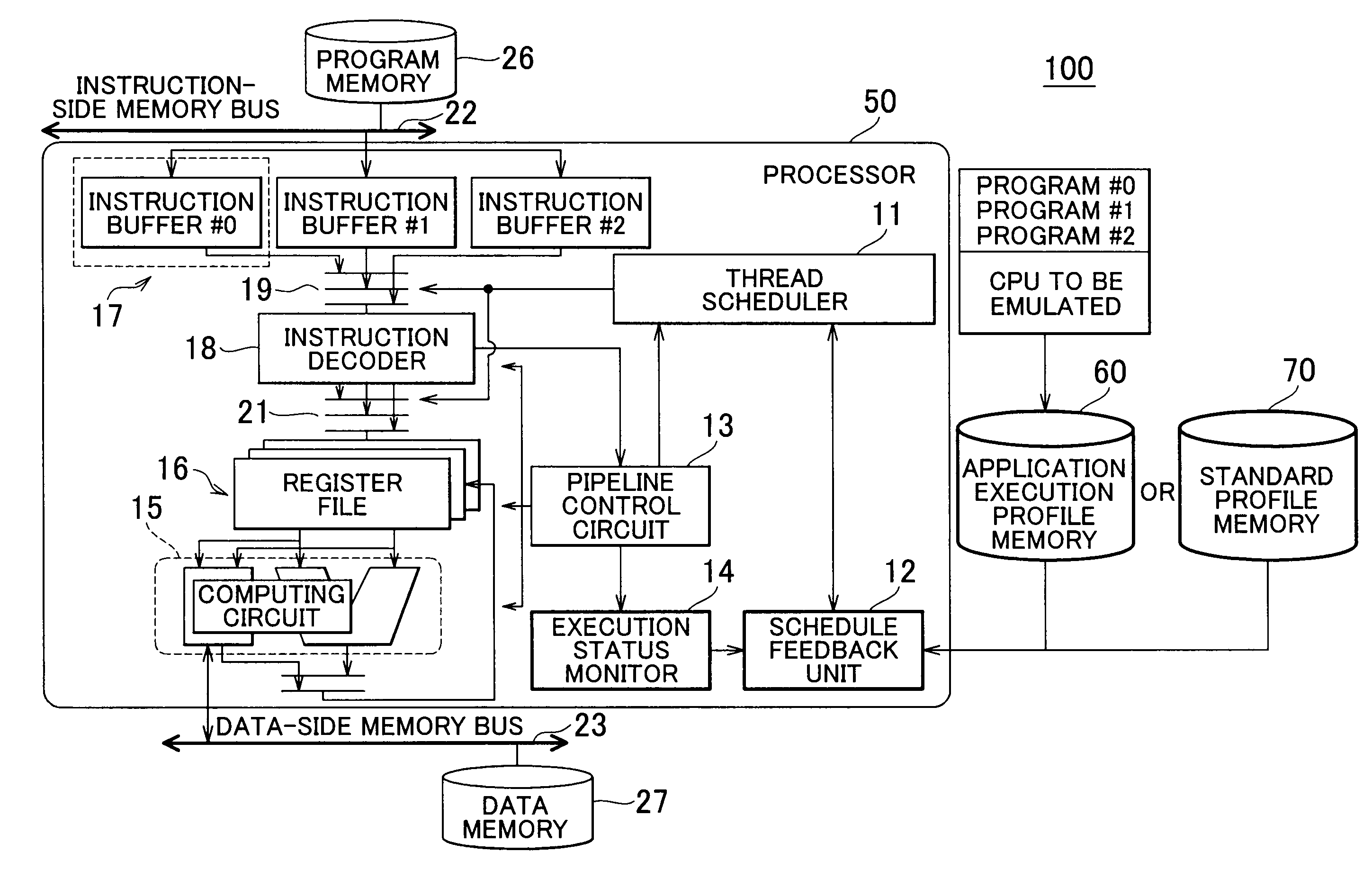
[0041]A first and a second embodiment of the present invention are described below with reference to the drawings. FIG. 3A is a schematic diagram of a multithread execution device 100 according to the first embodiment of the present invention. The outline of the procedures in which the multithread execution device 100 dynamically optimizes the execution number of a program will be described first. (1) An application execution profile or a standard profile (hereinafter referred to as a “target profile” unless these profiles are distinguished from each other) is provided.

[0042]The application execution profile, which will be described in detail later, is the number of instructions executed per unit time or the number of execute cycles per unit process of the program by a CPU before integration (hereinafter referred to as an emulated CPU). In other words, the application execution profile is information that indicates the execution speed of the emulated CPU. Meanwhile, the standard pro...


PUM


Abstract

A multithread execution device includes: a program memory in which a plurality of programs are stored; an instruction issue unit that issues an instruction retrieved from the program memory; an instruction execution unit that executes the instruction; a target execution speed information memory that stores target execution speed information of the instruction; an execution speed monitor that monitors an execution speed of the instruction; a feedback control unit that commands the instruction issue unit to issue the instruction such that the execution speed of the instruction approximately corresponds to the target execution speed information.

Description

INCORPORATION BY REFERENCE[0001]The disclosure of Japanese Patent Application No. 2009-138327 filed on Jun. 9, 2009 including the specification, drawings and abstract is incorporated herein by reference in its entirety.BACKGROUND OF THE INVENTION[0002]1. Field of the Invention[0003]The present invention relates to a multithread execution device that individually executes a plurality of programs and a method for executing multiple threads, and particularly, relates to a multithread execution device that adjusts the instruction issue rate for each program and a method for executing multiple threads.[0004]2. Description of the Related Art[0005]Various methods for efficiently executing a program are generally considered. Many of the approaches that improve execution efficiency attempt to shorten the time period in which a computing circuit of a CPU does not execute the program. For example, a technology to reduce branching or confirmation pending of the content of a process by a user op...

Claims


Application Information

Patent Timeline
Patent Type & Authority Applications(United States)
IPC IPC(8): G06F9/312G06F9/30
CPCG06F9/3851
Inventor WAKABAYASHI, TETSUAKIADACHI, KOJIOKAMOTO, KAZUYA
Owner RENESAS ELECTRONICS CORP
Learn More