Power control method for virtual machine and virtual computer system

a technology of virtual machines and computer systems, applied in program control, multi-programming arrangements, instruments, etc., can solve the problems of physical cpus not being able to control the host os, reducing power consumption, physical cpus, etc., to reduce the and reduce power consumption of physical computers.

Inactive Publication Date: 2009-06-11
HITACHI LTD
View PDF12 Cites 42 Cited by
  • Summary
  • Abstract
  • Description
  • Claims
  • Application Information

AI Technical Summary

Benefits of technology

[0006]In Non-patent Document 1, processing of allocating a virtual CPU to a physical CPU is dependent on a scheduler of the host OS (VM kernel). In JP 2006-113767 A, a guest OS is run on a management OS and the management OS executes the power control and clock control of a physical CPU according to an instruction from the guest OS so that the power consumption of virtual machines is reduced.
[0011]This invention has been made in view of the above, and it is therefore an object of this invention to reduce power consumption in a virtual computer system by controlling the association between a virtual CPU and a physical CPU in a manner that optimizes the number of physical CPUs to which no virtual CPUs are allocated throughout the virtual computer system.
[0013]In this way, when a virtual CPU is deleted after the virtual CPU is allocated to a logical partition and a physical CPU that has been allocated the deleted virtual CPU has no other virtual CPUs allocated, the physical CPU is put into a sleep state. This invention can thus actively reduce the power consumption of physical computers.
[0014]Further, in the case where a first physical CPU is allocated a second virtual CPU other than a deleted virtual CPU and it is possible to allocate the second virtual CPU to a second physical CPU which is in a normal state, the second virtual CPU is reallocated to the second physical CPU and the first physical CPU is shifted to a sleep state after no virtual CPUs remain allocated to the first physical CPU. Physical CPUs in a sleep state are thus created actively, and hence the power consumption of physical computers is reduced by optimizing virtual CPU allocation.
[0015]Furthermore, in the case where the virtual CPU operation ratio is to be obtained in reallocating the second virtual CPU to the second physical CPU, the virtual CPU allocation ratio can exceed 100% as long as the combined operation ratio of virtual CPUs allocated to the second physical CPU is smaller than a threshold. Virtual CPUs can thus be reallocated even more efficiently, and hence the power consumption of physical computers is reduced by maximizing the number of physical CPUs that are in a sleep state.

Problems solved by technology

In the conventional example of Non-patent Document 1, management of virtual CPUs and physical CPUs is performed by the host OS, which means that virtualization software running on the host OS cannot control physical CPUs in a manner that takes power consumption into consideration.
It is therefore difficult in this conventional example to reduce power consumption by controlling the allocation of virtual CPUs to physical CPUs with virtualization software.
This means that physical CPUs are always in operation and keep consuming power when there are no commands to be executed, in other words, when no virtual CPUs are allocated to the physical CPUs.

Method used


Image

  • Power control method for virtual machine and virtual computer system
  • Power control method for virtual machine and virtual computer system
  • Power control method for virtual machine and virtual computer system

Examples


second embodiment

[0086]FIGS. 7 to 9 illustrate a second embodiment of this invention in which the physical CPU control unit 330 of the first embodiment controls the operating clock of the physical CPUs 410 to 412, and the virtual CPU-physical CPU allocation unit 340 controls virtual CPU allocation in a manner that maximizes the number of physical CPUs in a sleep state when a virtual CPU is deleted. The configuration of the physical computer 400 in the second embodiment is the same as in the first embodiment. In the virtualization software 300 of the second embodiment, some of functions of the virtual CPU-physical CPU allocation unit 340 and the physical CPU control unit 330 differ from the first embodiment, and a virtual CPU-physical CPU allocation table 341A is structured in some parts differently from the virtual CPU-physical CPU allocation table 341 of the first embodiment.

[0087]FIG. 7 is an explanatory diagram illustrating the configuration of the virtual CPU-physical CPU allocation table 34IA w...

third embodiment

[0115]FIG. 11 is a flow chart illustrating an example of virtual CPU deleting processing that is executed by virtualization software according to a third embodiment of this invention. FIG. 11 is a partially modified version of the flow chart of FIG. 9 illustrating the virtual CPU deleting processing that is executed by the virtualization software 300 according to the second embodiment. The rest is the same as in the second embodiment.

[0116]The flow chart of FIG. 11 is obtained by inserting an additional step, Step S40, between Steps S32 and S33 of the flow chart of FIG. 9. Step S40 is a step of changing the operating clock frequency of the physical CPUs 410 to 412.

[0117]In Step S40, whether or not the operating clock frequency of one of the physical CPUs 410 to 412 that is currently selected can be changed is judged as in Steps S21 and S22 of FIG. 8 described in the second embodiment and, when it is possible, the operating clock frequency is changed to suit new allocation.

[0118]Spec...

fourth embodiment

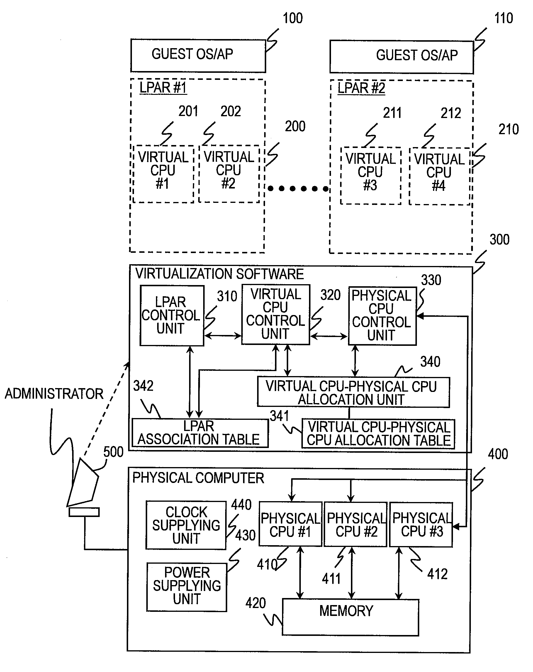
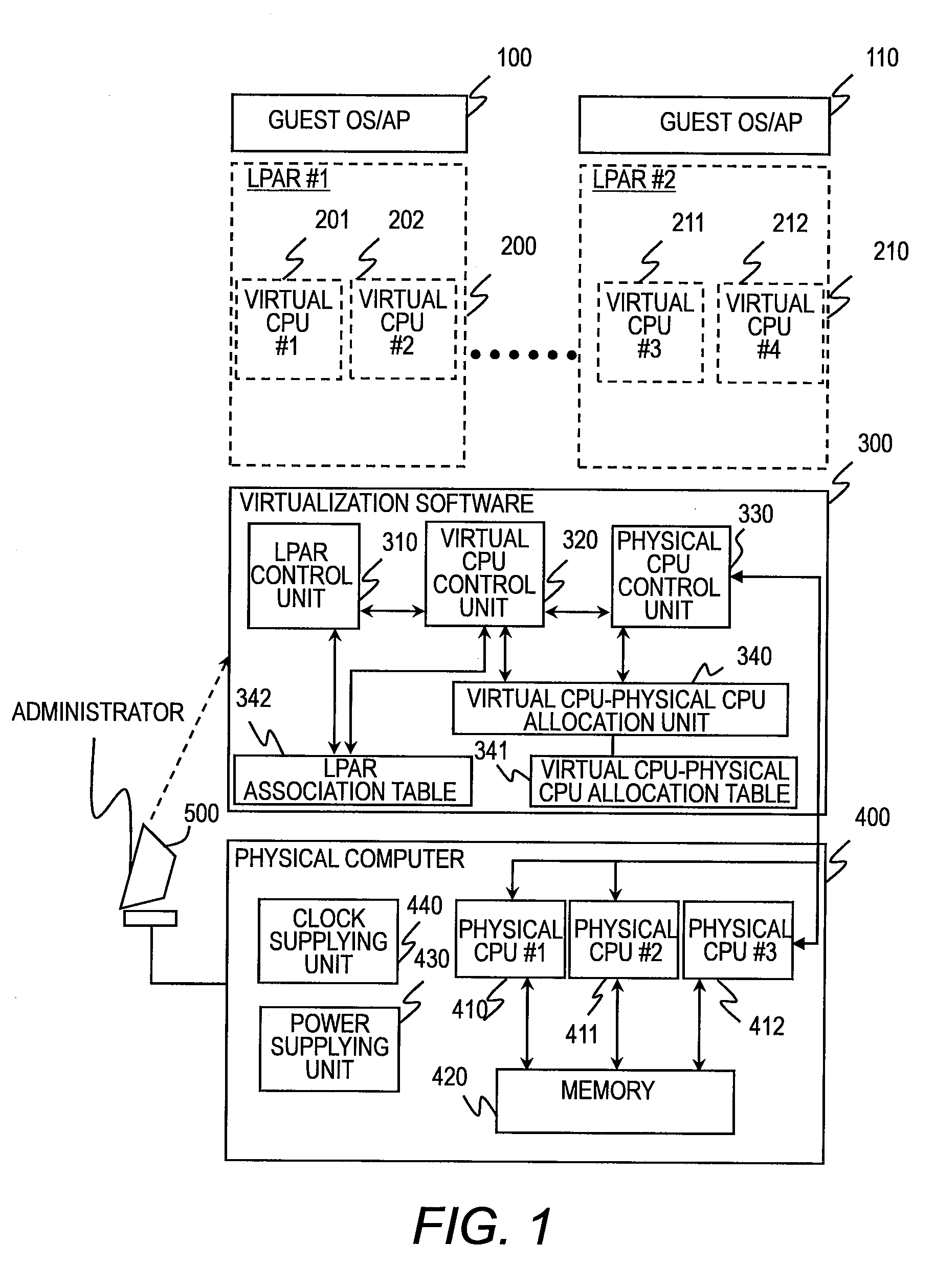
[0123]FIG. 13 is a block diagram illustrating a configuration of a virtual computer system according to a fourth embodiment of this invention. In FIG. 13, the virtual CPU utilization ratio (hereinafter referred to as operation ratio) of each guest OS is monitored by operation ratio monitoring middleware 500 and 510, which are run on the guest OSs 100 and 110 of the first embodiment and which notifies the virtualization software 300 of the operation ratio. The virtual CPU-physical CPU allocation unit 340 of the virtualization software 300 of FIG. 13 controls allocation of virtual CPUs to physical CPUs based on the virtual CPU operation ratio.

[0124]FIG. 14 is an explanatory diagram illustrating an example of a virtual CPU-physical CPU allocation table that is managed by virtualization software according to the fourth embodiment. The virtual CPU-physical CPU allocation unit 340 manages a virtual CPU-physical CPU allocation table 341B, which is, as illustrated in FIG. 14, obtained by ad...


PUM


Abstract

Provided is a method of controlling a virtual computer system in which a physical computer includes a plurality of physical CPUs that is switchable between a sleep state and a normal state, and a virtualization control unit divides the physical computer into a plurality of logical partitions to run a guest OS in each of the logical partitions and controls allocation of resources of the physical computer to the logical partitions, causes the virtualization control unit to: receive an operation instruction for operating the logical partitions; and if the operation instruction is for deleting a virtual CPU from one of the logical partitions, delete this virtual CPU from a table for managing virtual CPU-physical CPU allocation and put, if the deleting leaves no virtual CPUs allocated to one of the physical CPUs that has been allocated the deleted virtual CPU, this one of the physical CPUs into the sleep state.

Description

CLAIM OF PRIORITY[0001]The present application claims priority from Japanese application P2007-314761 filed on Dec. 5, 2007, the content of which is hereby incorporated by reference into this application.BACKGROUND OF THE INVENTION[0002]This invention relates to improving a type of virtual computer system that runs guest OSs on a plurality of physical computers.[0003]The recent computers consume more electric power as the performance of processors (CPUs) becomes higher. In particular, CPUs for server use which are equipped with a large-capacity cache memory have high performance but consume a great deal of power. Power consumption in a server where a plurality of CPUs are installed is even greater. In data centers and other facilities that run a large number of servers, large power consumption in the servers has an accordingly large influence on server installation conditions, cooling, and the like.[0004]IT systems using a server are generally designed according to the peak CPU perf...

Claims


Application Information

Patent Timeline
Patent Type & Authority Applications(United States)
IPC IPC(8): G06F9/50
CPCG06F1/3203G06F9/5027Y02B60/167G06F9/5094Y02B60/142G06F9/5077G06F9/45541G06F9/45558G06F2009/45575G06F2009/45579Y02D10/00
Inventor TSUSHIMA, YUJIUEHARA, KEITAROMORIKI, TOSHIOMIHATTORI, NAOYA
Owner HITACHI LTD
Why Eureka
Try Eureka