
Cab frame beltline member

Inactive Publication Date: 2010-12-16
DEERE & CO
View PDF18 Cites 13 Cited by
  • Summary
  • Abstract
  • Description
  • Claims
  • Application Information

AI Technical Summary

Benefits of technology

[0004]Accordingly, an object of this invention is to provide a simple yet robust beltline support for a ROPs cab frame.
[0005]A further object of the invention is to provide such a ROPs beltline support which creates more room in the cab interior.
[0006]These and other objects are achieved by the present invention, wherein a beltline support member is formed by two separate parts which are welded together. The support member includes a central portion, a left end fixed to the left rear corner post and a right end fixed to the right rear corner post. The central portion is curved or offset to the rear to allow for more room in the interior of the cab. The offset allows the seat to mover farther rearward, between the rear corner posts, thus creating a larger space for the operator.

Problems solved by technology

However, it appears that this cab frame structure does not include a ROPs sufficient beltline or beltline level support member between the rear corner posts, since the patent does not show any gusseting between a beltline level support member and the rear corner posts.

Method used


Image

  • Cab frame beltline member
  • Cab frame beltline member
  • Cab frame beltline member

Examples


Embodiment Construction

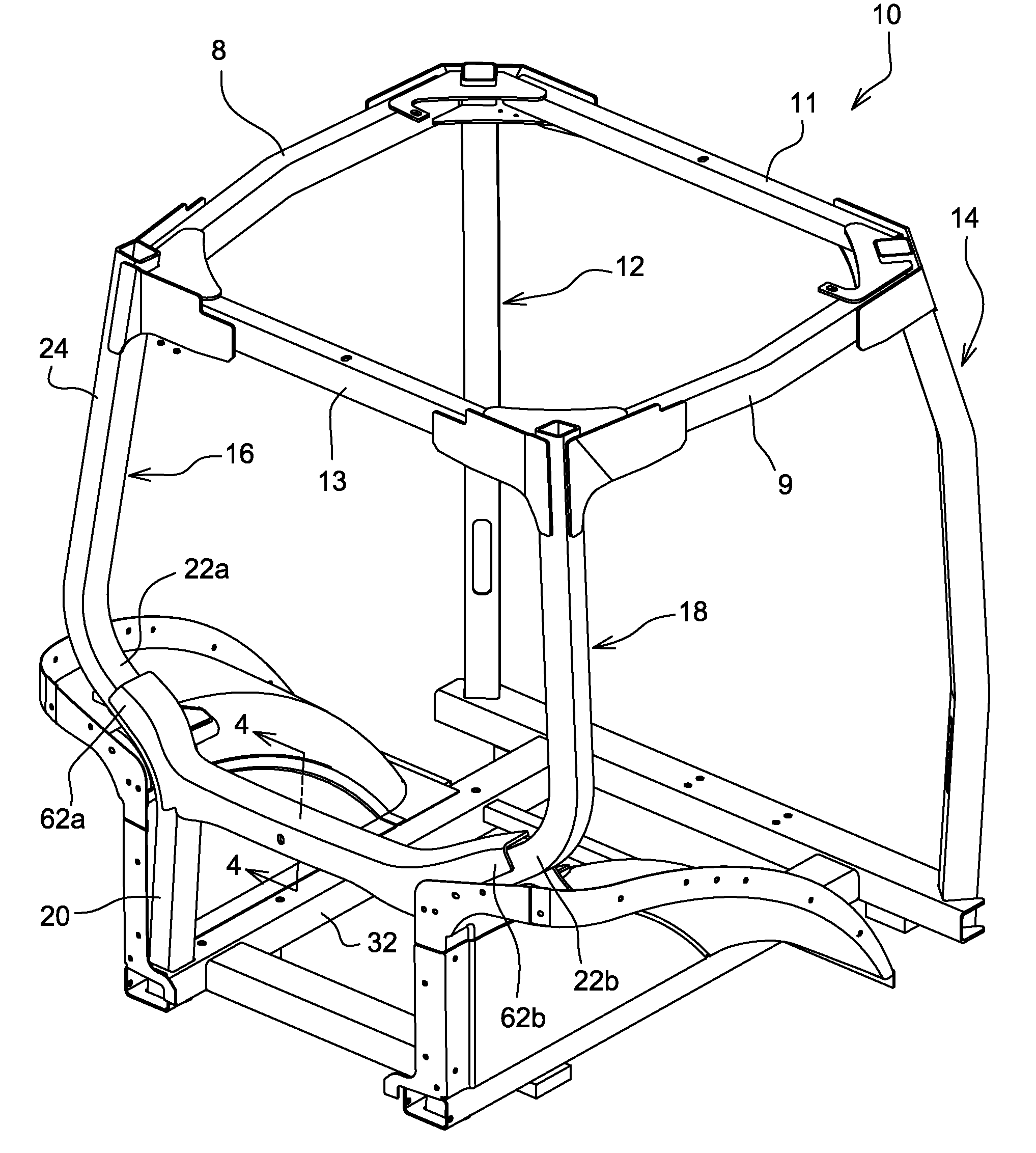
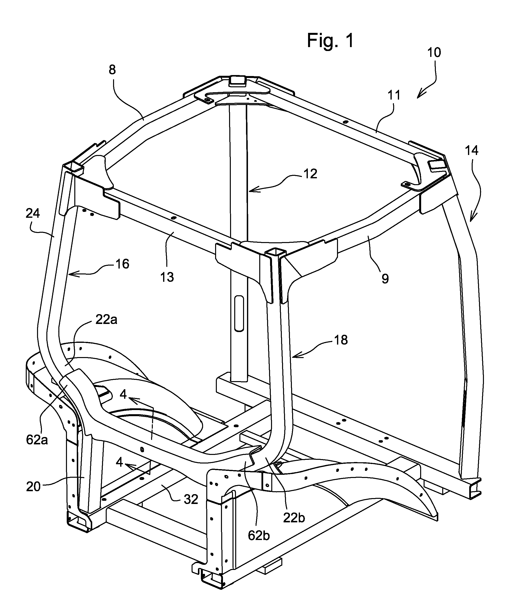
[0013]Referring to FIGS. 1-3, a ROPS-capable cab frame 10 for an agricultural vehicle, such as a tractor, includes left and right front corner posts 12 and 14, and left and right rear corner posts 16 and 18. The upper ends of these posts are joined together by upper side posts 8 and 9, upper front post 11 and upper rear post 13.

[0014]Each of the rear corner posts 16 and 18 are formed from a tube which is bent or curved to define lower portions 20a and 20b, slanted transition portions 22a and 22b and upper portions 24a and 24b. Lower portions 20a and 20b are positioned at the rear of the cab inwards of the rear wheel fenders 30a and 30b. The slanted transition portions 22a and 22b are between the lower portions 20a and 20b and the upper portions 24a and 24b.

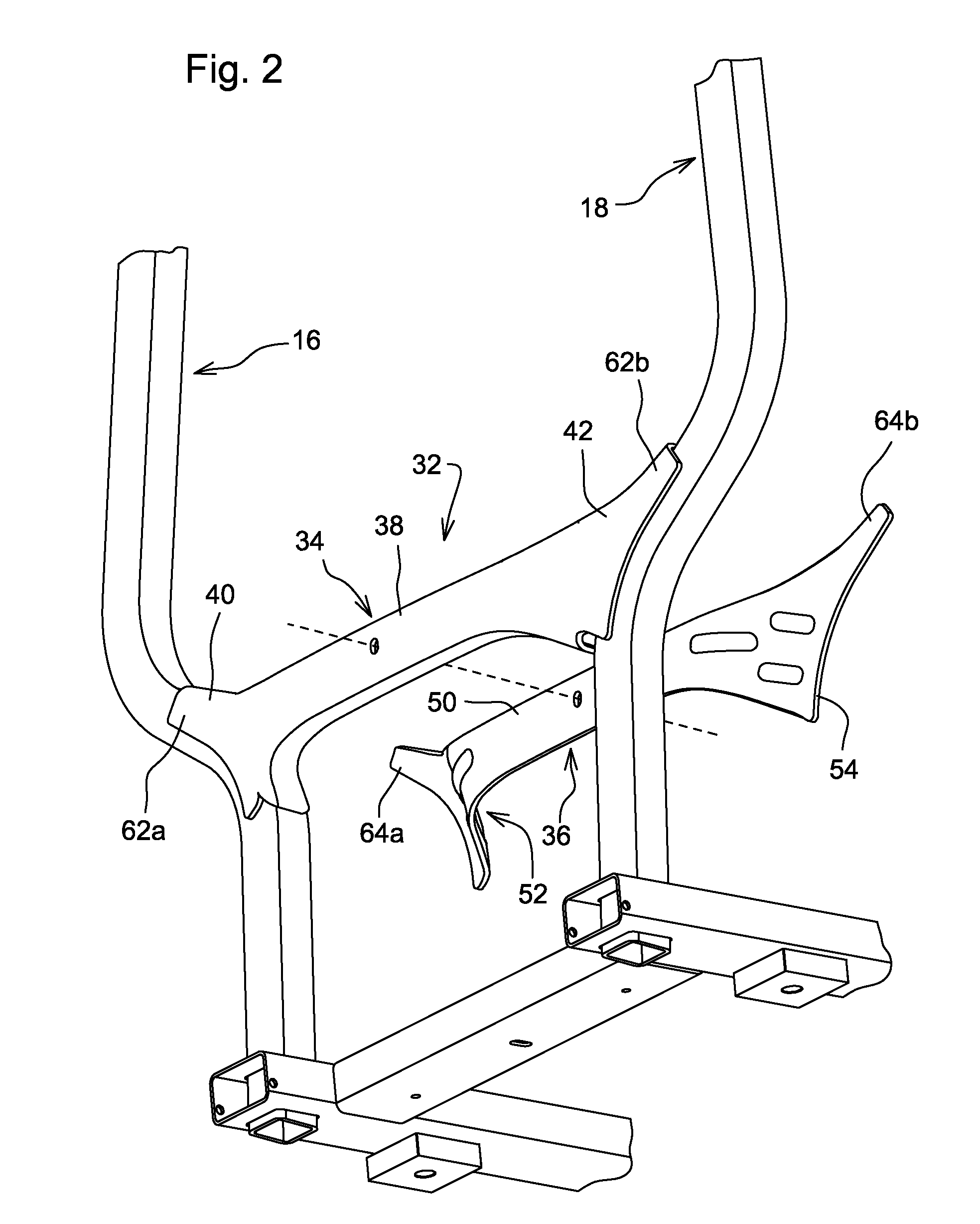
[0015]Transition portions 22a and 22b are joined together by a beltline or waist level member 32. Beltline member 32 includes a ROPS-capable rear beltline member 34 and a front beltline member 36 which are welded together, and wh...


PUM


Abstract

A ROPS-capable cab frame beltline support member for a vehicle cab frame which includes left and right rear corner posts. The beltline support member extends between the rear corner posts and is spaced apart above the lower ends of the posts. The support member includes first and second parts welded together. The support member includes a central portion, a left end fixed to the left rear corner post and a right end fixed to the right rear corner post. The central portion is offset rearwardly with respect to its left and right ends. The first part includes a midportion, a left flange portion and a right flange portion. The midportion has a C-shaped cross sectional shape. The midportion of the first part has a wider upper side, a back plate and a narrower lower side. The second part includes flanged ends and an elongated member having a first edge which engages an inner surface of the first part, and having a side surface which engages an edge of the first part. The flange portions are attached to slanted transition portions of the corner posts and form gussets between the rear corner posts and the beltline support member.

Description

FIELD OF THE INVENTION[0001]The present invention relates to a cab frame structure for vehicles such as large agricultural tractors, and more specifically to a beltline member for a cab frame structure which is capable of providing roll-over protective (ROP).BACKGROUND OF THE INVENTION[0002]A cab frame structure is shown in U.S. Pat. No. 6,543,840, issued in April 2003 to Collier et al. However, it appears that this cab frame structure does not include a ROPs sufficient beltline or beltline level support member between the rear corner posts, since the patent does not show any gusseting between a beltline level support member and the rear corner posts.[0003]Large agricultural tractors have cab frames which are designed to perform as roll-over protective structures or ROPS. In such structures the beltline area requires a lot of support between the rear corner posts due to the significant loads being transferred from the upper portion of the cab frame to the cab mounting structure. The...

Claims


Application Information

Patent Timeline
IPC IPC(8): B62D33/06B62D25/00E02F9/16
CPCB62D33/0617
Inventor WOOD, JR., ROBERT LEELANDERS, TRACE DUSTINMUGGE, WAYNE DOUGLASWARREN, CHARLES NICHOLAS
Owner DEERE & CO
Learn More