
Connector box partly embedded in a fibre-reinforced part for protecting and connecting purposes

a fibre-reinforced part and connector box technology, applied in the field of connector boxes, can solve the problems of increasing the risk of a malfunctioning element which is difficult or impossible to repair, unavoidably reducing the quality of the injection of resin and thus the overall quality of the fibre-reinforced structure, and reducing the cost of production and end-products. , to achieve the effect of good manufacturing properties, low weight and easy cutting or ripping

Inactive Publication Date: 2010-06-01
LM GLASSFIBER
View PDF9 Cites 10 Cited by
  • Summary
  • Abstract
  • Description
  • Claims
  • Application Information

AI Technical Summary

Benefits of technology

The connector box ensures robust embedding without compromising structural strength, protects vulnerable elements, and allows for easy and safe connection of external devices post-manufacturing, reducing production costs and improving product quality by eliminating the need for cutting vacuum foils and minimizing damage risks.

Problems solved by technology

It is, however, a problem when the element is to be connected to another part and thus must protrude from the fibre-reinforcement in some way to be accessible from the outside.
However, this unavoidably reduces the quality of the injection of the resin and thus the overall quality of the fibre-reinforced structure.
Furthermore, the element is easy to damage by this handling and is vulnerable during the injection, thus increasing the cost of the production and the end-product as well as increasing the risk of a malfunctioning element which is difficult or impossible to repair as the element is embedded in the structure.

Method used


Image

  • Connector box partly embedded in a fibre-reinforced part for protecting and connecting purposes
  • Connector box partly embedded in a fibre-reinforced part for protecting and connecting purposes
  • Connector box partly embedded in a fibre-reinforced part for protecting and connecting purposes

Examples


Embodiment Construction

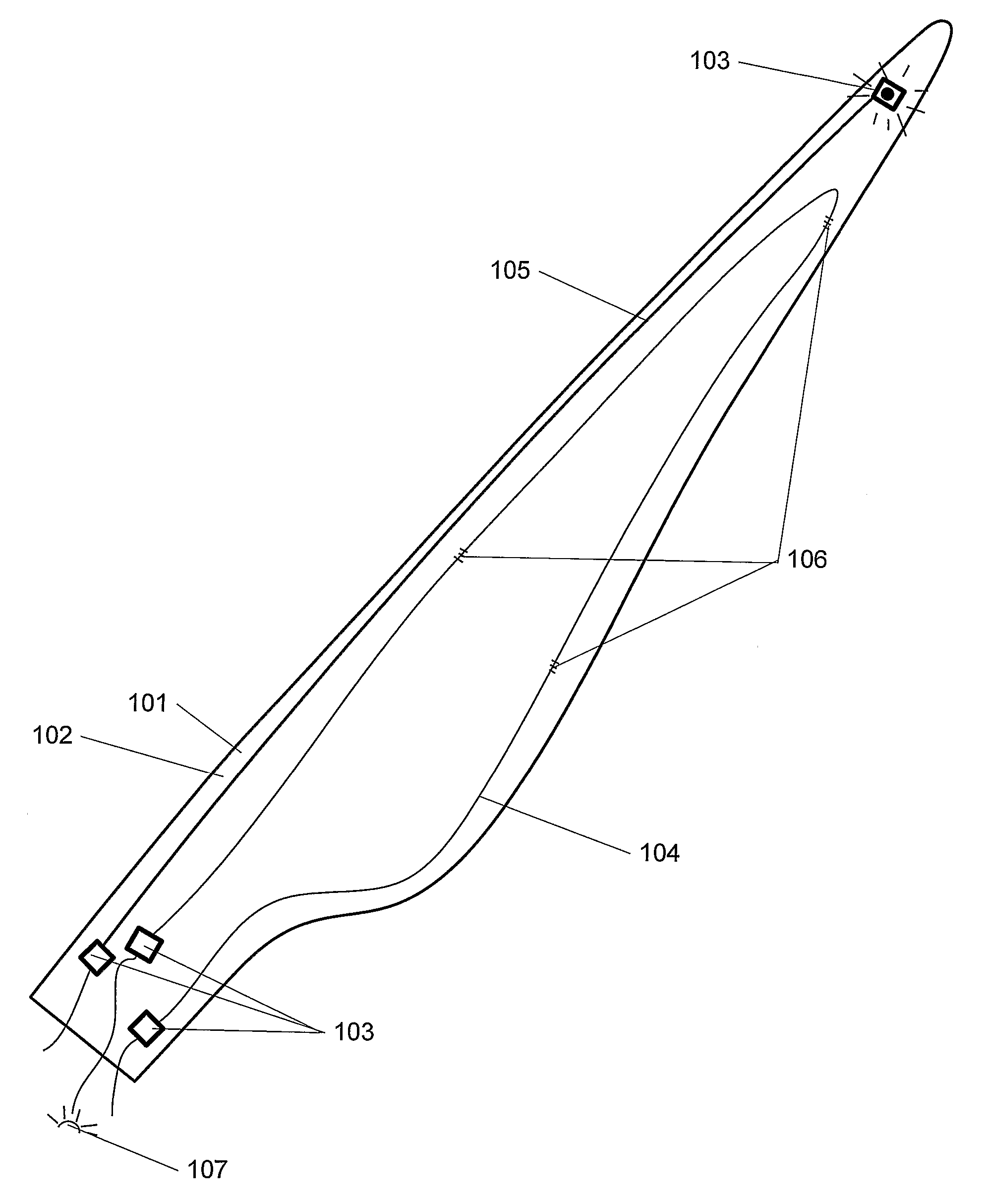
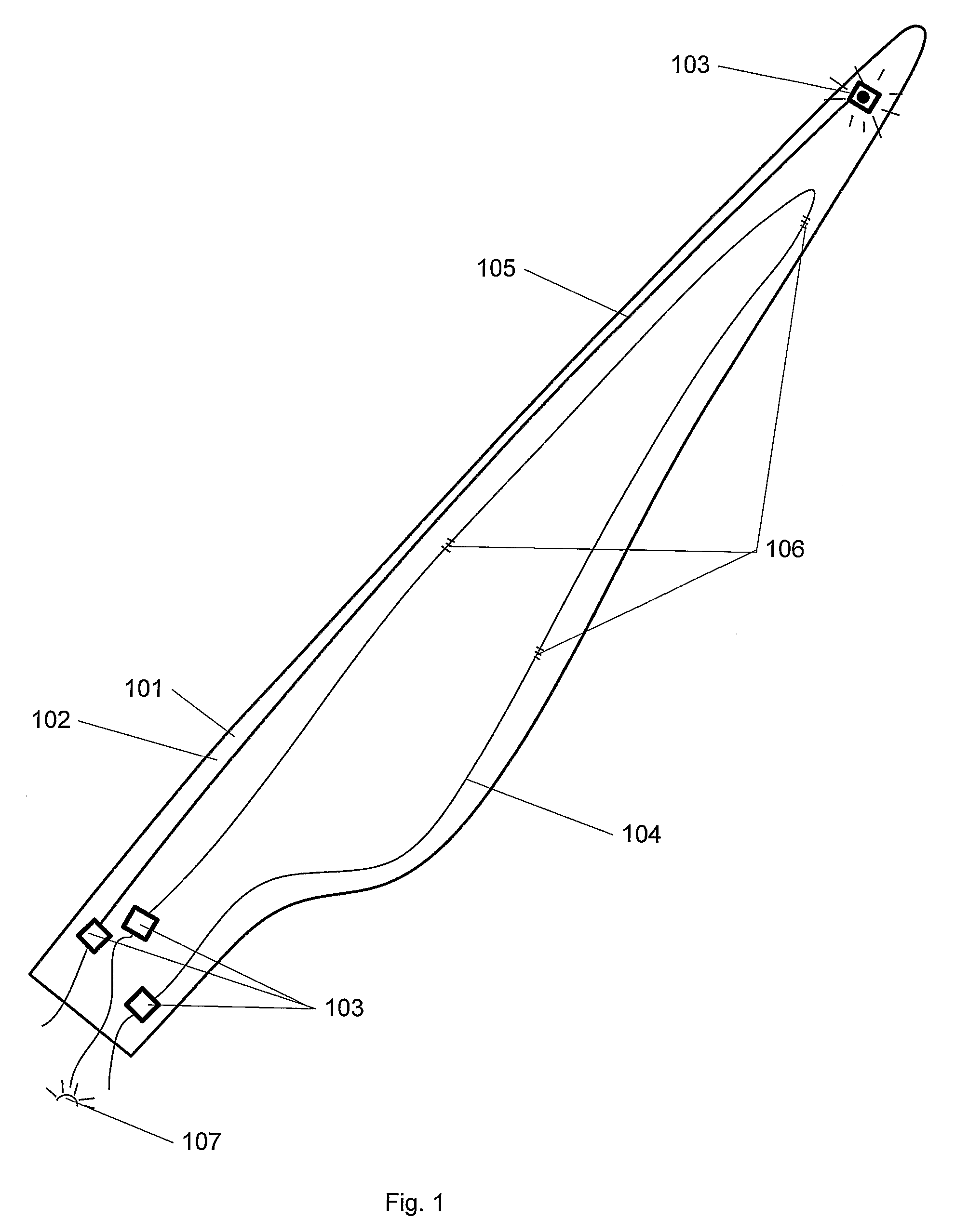
[0024]FIG. 1 displays a blade 101 for a wind turbine comprising a fibre-reinforced blade shell 102. A number of connector boxes 103 are in this design placed near the root and near the tip of the blade, respectively. Two of the boxes near the root of the blade are connected to the ends of an optical fibre 104. An electrical wire 105 is led from the root to the tip and connected to a box in each end running in this sketched embodiment along the length of the blade. Such an electrical wire 105 embedded partly or totally in the blade could be used, for instance, for applying obstructing lights on the blade tip, or used to connect to and run some other sensor or device with a technical feature. The optical fibre 104 can among other things be used for measuring the strains and temperatures at positions on the blade, where a number of Bragg gratings 106 (illustrated by small hatches) are placed in the fibre. The fibre is then connected to light emission and / or light receiving means 107 in...


PUM

PropertyMeasurementUnit
circumferenceaaaaaaaaaa
currentaaaaaaaaaa
flexibleaaaaaaaaaa

Abstract

The present invention relates to a connector box adapted to be at least partly embedded in a fiber-reinforced part of a wind turbine, where said connector box comprises a flexible base part and a sealing part. The sealing part seals off and protects at least one compartment between the sealing part and the base part during manufacture of said fiber-reinforced part, but can be partly removed after manufacture making said compartment accessible. The base part is adapted to fasten the connector box in the fiber-reinforced part by having a larger circumference near its bottom than near its top. Further, the invention relates to such a connector box fixating a part of an element in the compartment of the box and making a second part of the element accessible from the compartment after manufacture.

Description

FIELD OF THE INVENTION[0001]The present invention concerns a connector box adapted to be at least partly embedded in a fibre-reinforced part of a wind turbine with the purpose of protecting sensitive parts during manufacture and enabling accessibility after the manufacture. The invention further relates to a blade for a wind turbine containing such connector boxes.BACKGROUND OF THE INVENTION[0002]Sensors and other means for measurements are often connected to large fibre-reinforced structures such as parts for wind turbines, ship hulls, parts on aircrafts, etc. This includes, for instance, strain gauges for measuring the loads on the structure and its response, devices for temperature or pressure measurements, GPS receivers, lights, lightning conductors, data registration units, etc. The application of such devices or sensors then also naturally in most cases requires the guiding of elements for their functioning such as electrical wires, optical fibres, cables or the like going fro...

Claims


Application Information

Patent Timeline
Patent Type & Authority Patents(United States)
IPC IPC(8): B64C27/473F01D5/14F03D11/00G01B11/16G01L1/24G01M11/08
CPCF03D11/00G01L1/26G01L1/246G01M11/086Y02E10/722F03D80/00F03D80/85Y02E10/72Y02P70/50
Inventor MORTENSEN, IVAN ENGMARKJENSEN, LARS ERIK
Owner LM GLASSFIBER
Learn More