
Adjustable propeller arrangement and a method of distributing fluid to and/or from such an adjustable propeller arrangement

a propeller arrangement and fluid distribution technology, applied in the direction of propellers, propulsive elements, water-acting propulsive elements, etc., can solve the problems of cumbersome manufacture, low fluid connection efficiency, and the inability to adjust the propeller arrangement, so as to achieve simple yet robust fluid connection

Inactive Publication Date: 2011-08-04
CATERPILLAR PROPULSION PRODION
View PDF9 Cites 2 Cited by
  • Summary
  • Abstract
  • Description
  • Claims
  • Application Information

AI Technical Summary

Benefits of technology

[0009]A first object of the present invention is to provide an adjustable propeller arrangement which arrangement comprises a drive shaft and which provides a simple yet robust fluid connection between a duct located outside the drive shaft and a conduit located at least partially within the drive shaft.
[0010]A second object of the present invention is to provide an adjustable propeller arrangement, wherein the arrangement is scalable such that the design of which may be adjusted to provide fluid communications between a plurality of ducts located outside the drive shaft and a plurality of conduits located at least partially within the drive shaft without unduly increasing the complexity and / or size of the distribution system.

Problems solved by technology

The connection arrangement disclosed in '940 may be cumbersome to manufacture since it includes a large number of cavities, gaps and spaces.
Moreover, due to the complexity of the connection arrangement, the '940 propeller arrangement will be relatively expensive and heavy.
Additionally, the '940 connection arrangement requires that a plurality of radially openings be provided in the drive shaft, or at least in an intermediate shaft forming a part of the drive shaft, which openings may impair the strength, in particular the torsional strength, of the drive shaft.

Method used


Image

  • Adjustable propeller arrangement and a method of distributing fluid to and/or from such an adjustable propeller arrangement
  • Adjustable propeller arrangement and a method of distributing fluid to and/or from such an adjustable propeller arrangement
  • Adjustable propeller arrangement and a method of distributing fluid to and/or from such an adjustable propeller arrangement

Examples


Embodiment Construction

[0038]The invention will be described using examples of embodiments. It should however be realized that the embodiments are included in order to explain principles of the invention and not to limit the scope of the invention, defined by the appended claims.

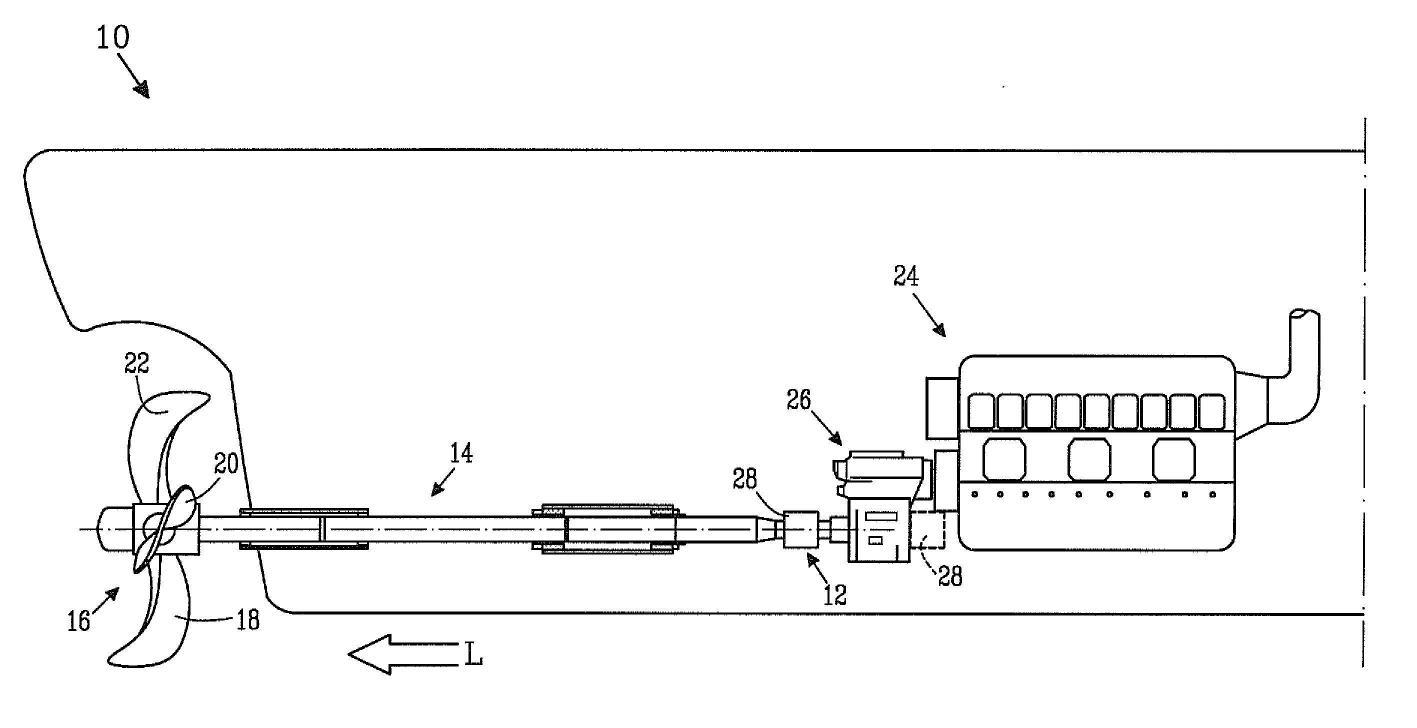
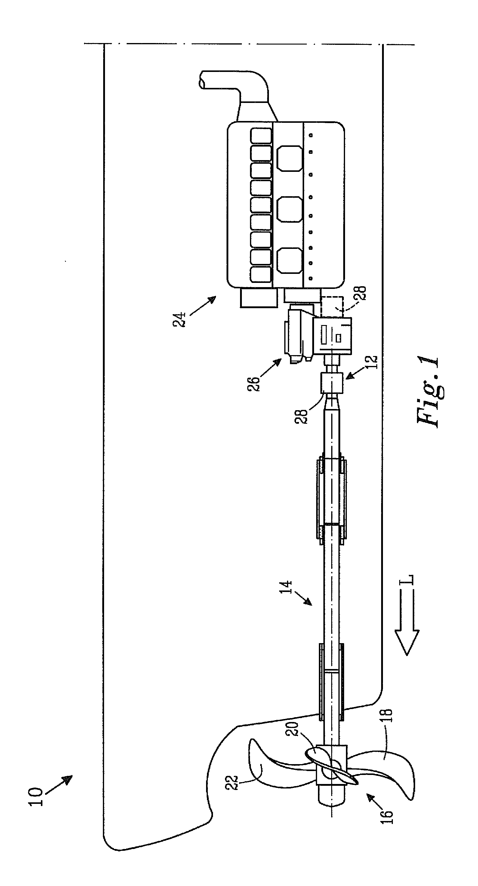
[0039]FIG. 1 illustrates a schematic side view of a vessel 10 comprising an adjustable propeller arrangement 12. As may be gleaned from FIG. 1, the arrangement 12 comprises a drive shaft 14 extending in a longitudinal direction L and an adjustable propeller 16 connected to the drive shaft 14. The adjustable propeller comprises at least one propeller blade, in the embodiment of the adjustable propeller illustrated in FIG. 1, the propeller includes four propeller blades three of which 18, 20, 22 are visible in FIG. 1. However, other implementations of propellers with more or fewer propeller blades may also be used with the propeller arrangement of the present invention. Furthermore, the vessel 10 may in some applications be provided...


PUM


Abstract

The present invention relates to an adjustable propeller arrangement comprising a drive shaft extending in a longitudinal direction and an adjustable propeller connected to the drive shaft. The adjustable propeller comprises at least one propeller blade and an adjusting member connected to the at least one propeller blade such that the pitch if the at least one propeller blade is controlled by the position, in the longitudinal direction, of the adjusting member. The arrangement comprises a conduit assembly which in turn comprises a duct located outside of the drive shaft and the conduit assembly further comprises a first conduit portion extending at least partially within the drive shaft. The conduit assembly is adapted to provide a fluid communication between the adjustable propeller and the duct.

Description

TECHNICAL FIELD[0001]The present invention relates to an adjustable propeller arrangement comprising a drive shaft extending in a longitudinal direction and an adjustable propeller connected to the drive shaft. The adjustable propeller comprises at least one propeller blade and an adjusting member connected to the at least one propeller blade such that the pitch of the at least one propeller blade is controlled by the position, in the longitudinal direction, of the adjusting member. The arrangement comprises a conduit assembly which in turn comprises a duct located outside of the drive shaft and the conduit assembly further comprises a first conduit portion extending at least partially within the drive shaft. The conduit assembly is adapted to provide a fluid communication between the adjustable propeller and the duct.[0002]The present invention also relates to a method of distributing fluid to and / or from an adjustable propeller arrangement.BACKGROUND OF THE INVENTION[0003]Floating...

Claims


Application Information

Patent Timeline
Patent Type & Authority Applications(United States)
IPC IPC(8): B63H3/00B64C11/38
CPCB63H3/08B63H3/04B63H3/082Y02E10/72
Inventor THYBERG, CONNY
Owner CATERPILLAR PROPULSION PRODION
Learn More