Imaging apparatus and imaging control method
a technology of imaging control and imaging apparatus, which is applied in the direction of color television details, television systems, instruments, etc., can solve the problems of out of focus, focusing position cannot be determined accurately, focusing position is misdetected,
- Summary
- Abstract
- Description
- Claims
- Application Information
AI Technical Summary
Benefits of technology
Problems solved by technology
Method used
Image
Examples
first embodiment
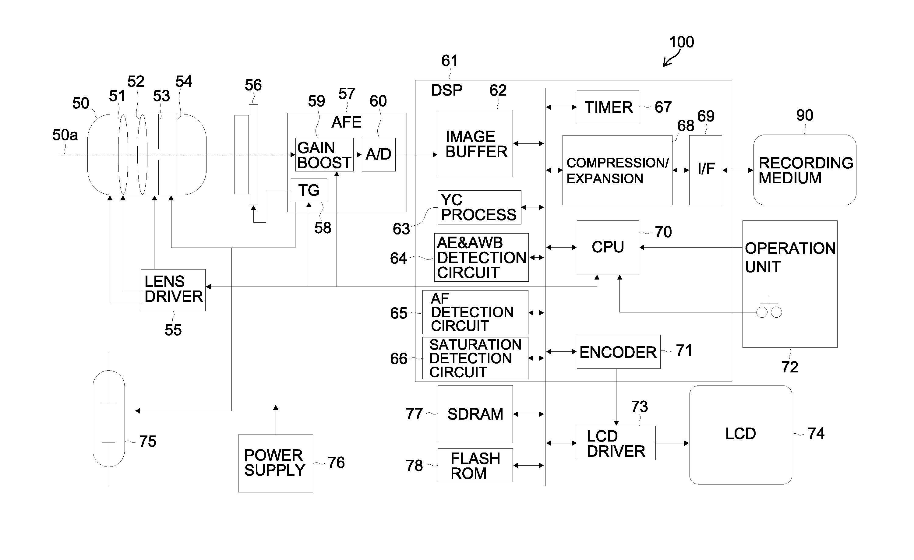
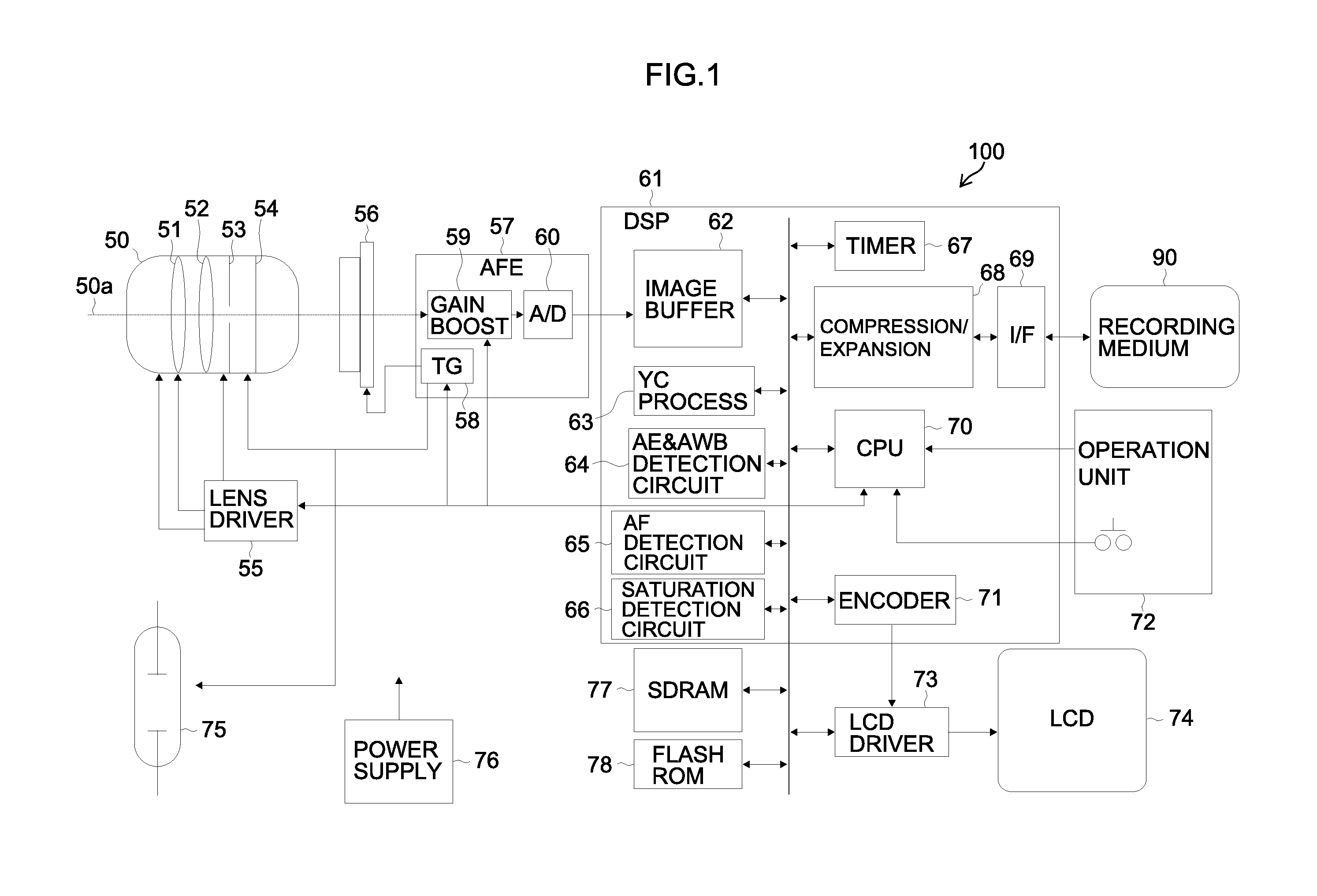
[0058]FIG. 1 is a block diagram illustrating an entire configuration of a digital camera 100 as an example of an imaging apparatus according to a first embodiment of the presently disclosed subject matter.
[0059]An imaging optical system 50 is configured to include a zoom lens 51, a focus lens 52, an iris 53, and a mechanical shutter 54. A lens driver 55 is configured to include a motor and a drive circuit and drives the zoom lens 51, the focus lens 52, and the iris 53 of the imaging optical system 50. A CCD (Charge Coupled Device) image sensor 56 images an object image focused by the imaging optical system 50. The zoom lens 51 is driven by the lens driver 55 and moves along an optical axis 50a of the imaging optical system 50. Thereby, an object image focused on a light receiving surface of the CCD image sensor 56 is optically variably magnified. The focus lens 52 is driven by the lens driver 55 and moves along the optical axis 50a of the imaging optical system 50. Thereby, focusing...
second embodiment
[0105]Now, the second embodiment will be described. The following description focuses only on a portion different from that of the first embodiment. The present embodiment is different in the AF search area setting from the first embodiment.
[0106]FIG. 11 illustrates a saturation detection area 231 and FIG. 12 illustrates AF search areas 241 and 242. In the AF search area setting (in step S35 of FIG. 4), a first AF search area 241 is set in the center of the image area 200 as illustrated in FIG. 12. The second AF search area 242 is larger in size than the first AF search area 241 and is not overlapped with the first AF search area 241. According to the present embodiment, the second AF search area 242 is arranged around the first AF search area 241.
[0107]Note that the saturation detection area 231 illustrated in FIG. 11 has the same position and size as the first AF search area 241. However, the size of the saturation detection area 231 may be slightly larger than the size of the fir...
third embodiment
[0109]Now, the third embodiment will be described. The following description focuses only on a portion different from that of the first embodiment. The present embodiment is different from the first embodiment in the saturation detection area setting, the AF search area setting, the point light source detection process, and the focusing determination area selection.
[0110]FIG. 13 illustrates an example of a saturation detection area arrangement, and FIG. 14 illustrates an example of an AF search area arrangement.
[0111]In the saturation detection area setting (in step S32 of FIG. 4), a 7×7 matrix of divided areas (numbers 0 to 48) arranged two-dimensionally in a vertical direction and a horizontal direction in the image area 200 is set as a saturation detection area 251 as illustrated in FIG. 13. That is, a plurality of saturation detection areas 251 not overlapped to each other with respect to the imaging image is set. The size of each of the plurality of divided areas is the same. N...
PUM
 Abstract
Description
Claims
Application Information
 - R&D
- Intellectual Property
- Life Sciences
- Materials
- Tech Scout
- Unparalleled Data Quality
- Higher Quality Content
- 60% Fewer Hallucinations
Browse by: Latest US Patents, China's latest patents, Technical Efficacy Thesaurus, Application Domain, Technology Topic, Popular Technical Reports.
© 2025 PatSnap. All rights reserved.Legal|Privacy policy|Modern Slavery Act Transparency Statement|Sitemap|About US| Contact US: help@patsnap.com


