Divided LED lamp

a technology of led lamps and diodes, which is applied in the field of electric lighting, can solve the problems of deteriorating operation stability, affecting the life of lamps, and not being able to achieve the desired heat dissipation performance, etc., and achieves the effects of stable operation, extended lifespan, and high heat dissipation efficiency

Inactive Publication Date: 2010-12-16
GUANGZHOU YAJIANG PHOTOELECTRIC EQUIP CO LTD
View PDF2 Cites 42 Cited by
  • Summary
  • Abstract
  • Description
  • Claims
  • Application Information

AI Technical Summary

Benefits of technology

[0003]To overcome the above discussed problems, the present invention provides a divided LED lamp, which allows LED assemblies and LED electronics to be received in individual and independent casing members and associated with respective heat dissipation fins or heat radiator, so as to realize high efficiency of heat dissipation, stabilized operation, and extended lifespan.

Problems solved by technology

Intense sun light and rainwater occurring in an outdoor environment set direct influences on the performance of an LED lamp and more particularly, the lifespan of the lamp is also affected.
This arrangement of heat dissipation often leads to combination of the heats generated by the LED assembly and the LED electronics, eventually resulting in overloading of the heat radiator, making it not possible to achieve the desired performance of heat dissipation.
Further, the LED assembly, which requires a great amount of heat to be removed may transfer excessive heat generated thereby through the heat radiator to the LED electronics, making the temperature of the LED electronics raised and eventually deteriorating operation stability of the LED electronics and shortening the lifespan of the LED electronics.

Method used


Image

  • Divided LED lamp
  • Divided LED lamp
  • Divided LED lamp

Examples


Embodiment Construction

[0024]The following descriptions are exemplary embodiments only, and are not intended to limit the scope, applicability or configuration of the invention in any way. Rather, the following description provides a convenient illustration for implementing exemplary embodiments of the invention. Various changes to the described embodiments may be made in the function and arrangement of the elements described without departing from the scope of the invention as set forth in the appended claims.

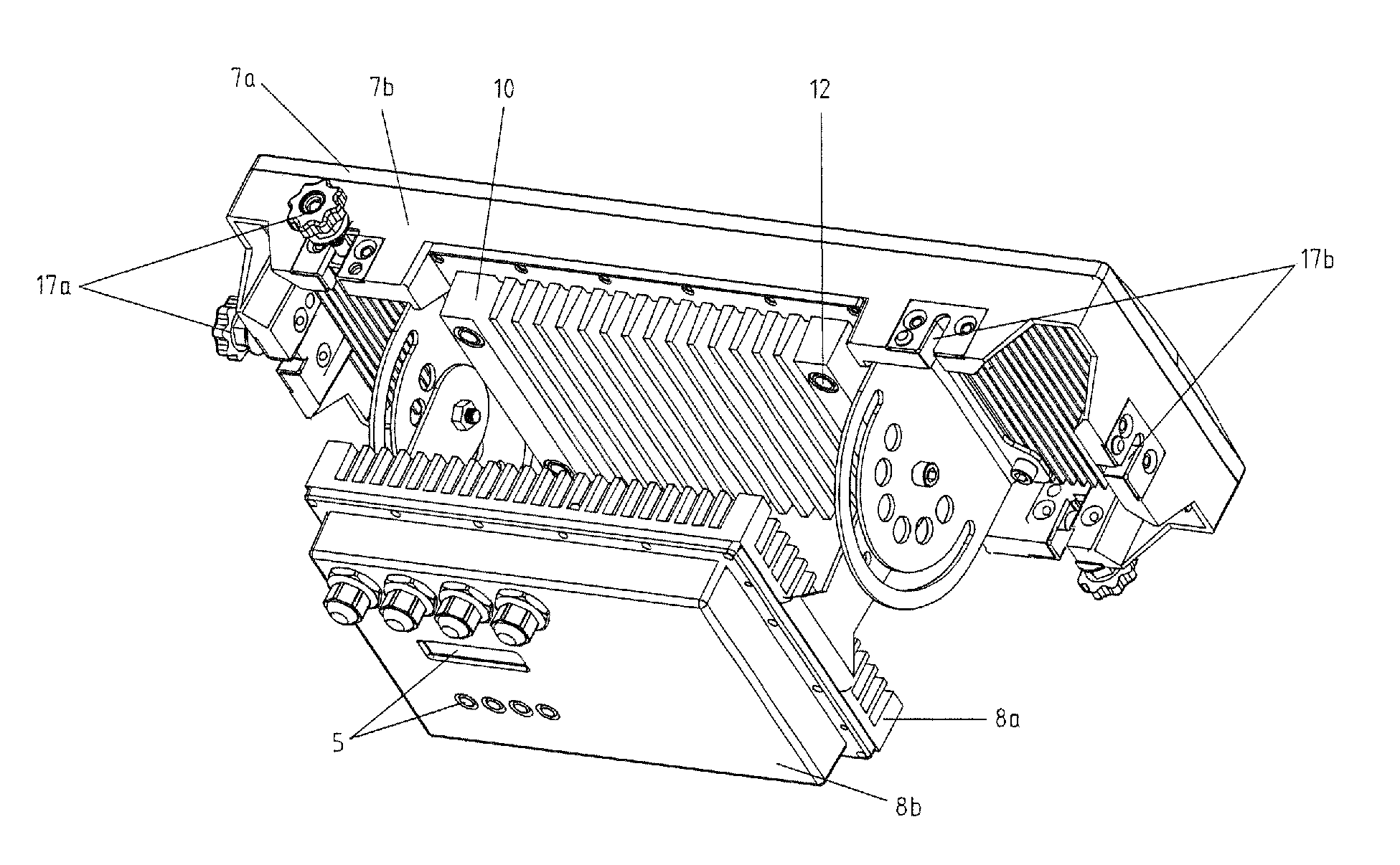
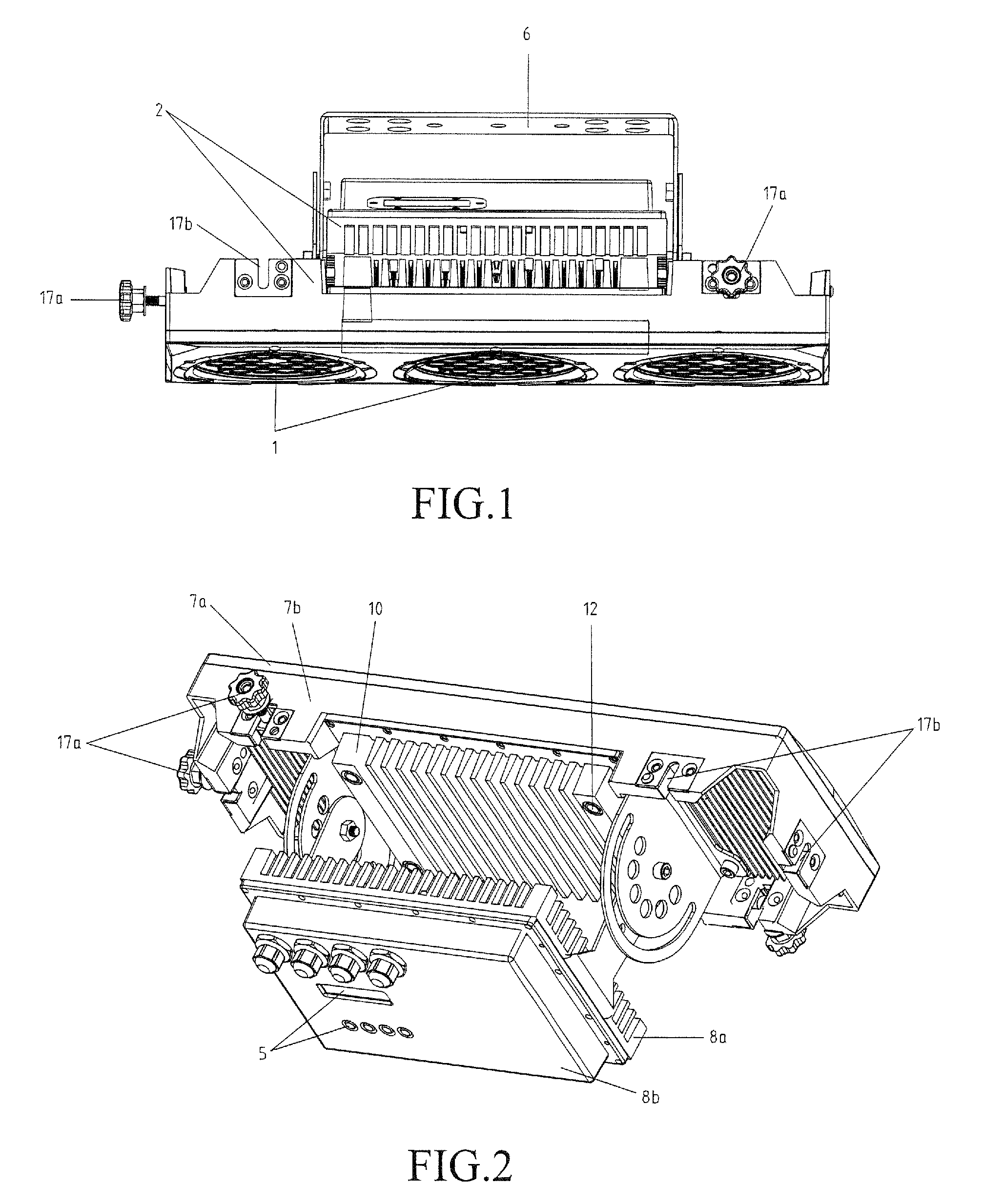
[0025]As shown in FIG. 1, the present invention provides a divided LED lamp, which comprises LED assemblies 1, a casing assembly 2, LED electronics 3, power and signal cables 4, a control panel 5 comprising a display screen and operation buttons, and a bracket 6 for mounting the LED lamp.

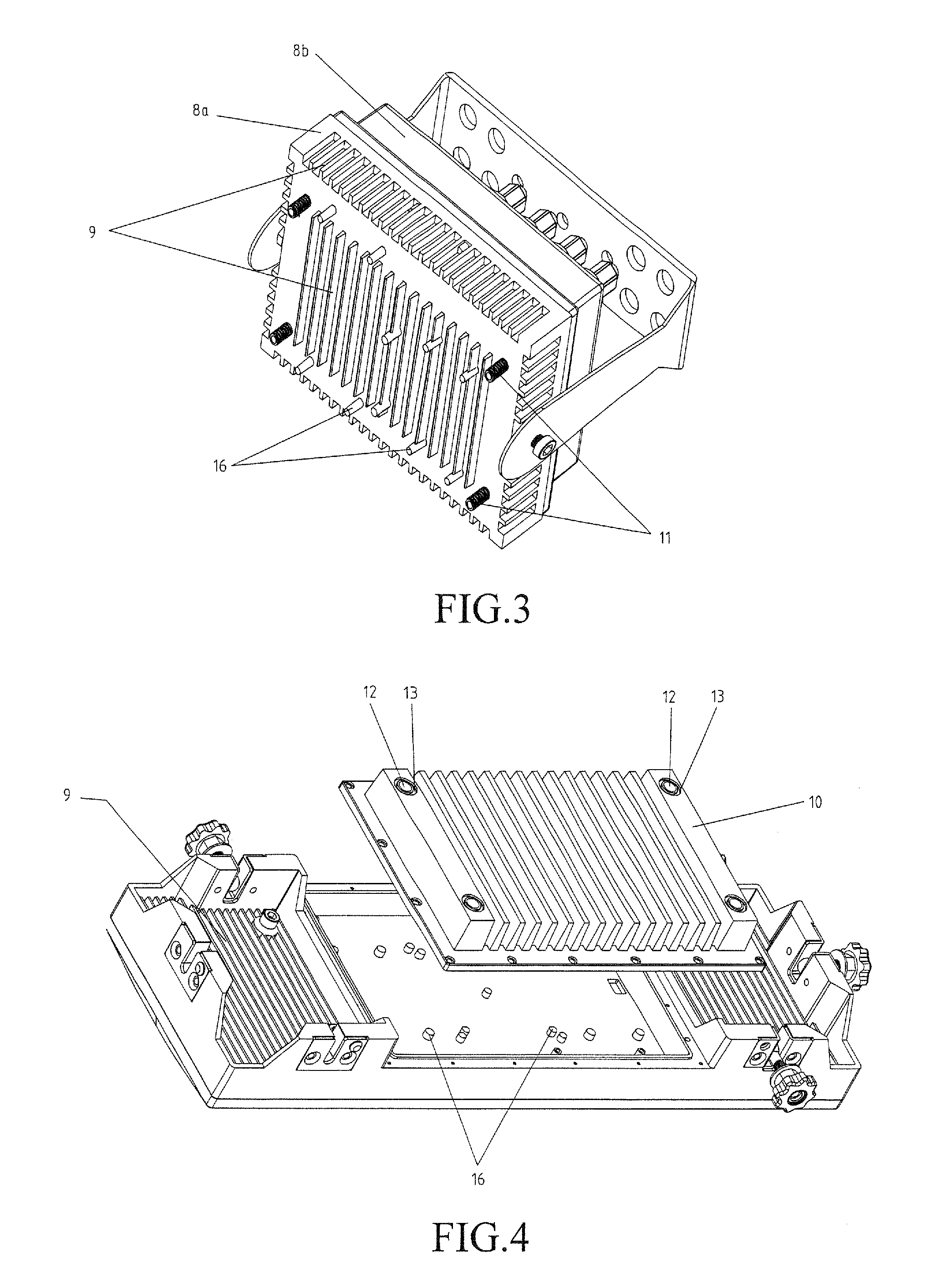
[0026]As shown in FIGS. 1-4, the casing assembly 2 is composed of a first casing member 7 and a second casing member 8. The first casing member 7 is composed of a front panel 7a and a first rear shell 7b. The LED as...


PUM


Abstract

A divided LED lamp includes an LED assembly, a casing assembly, LED electronics, power and signal cables, a control panel including a display screen and operation buttons, and a bracket for mounting the lamp. The casing assembly includes a first casing member and a second casing member. At least one cable tube is formed between the first casing member and the second casing member. The power and signal cables that connect the LED assembly received in the first casing member and the LED electronics received in the second casing member are received through the cable tube. This arrangement allows the LED assembly and the LED electronics to be received in individual and independent casing members and are associated with respective individual heat dissipation fins or heat radiators, so as to realize high efficiency of heat dissipation, stabilized operation, and extended lifespan.

Description

(a) TECHNICAL FIELD OF THE INVENTION[0001]The present invention generally relates to the field of electrical lighting, and more particularly to an LED (Light-Emitting Diode) lamp and especially a divided LED lamp of which heat dissipations for LED assemblies and LED electronics are performed separately.(b) DESCRIPTION OF THE PRIOR ART[0002]With the continuous development of LED (Light-Emitting Diode) technology LED lamps are now widely used in the field of lighting, especially for outdoor lighting, including commercial zones, high buildings, and landscape sites of cities, which use LED lamps for lighting purposes in nighttimes, site lighting, and color lighting. The outdoor LED lighting faces two major challenges, of which one is heat dissipation and the second is water resistance. Intense sun light and rainwater occurring in an outdoor environment set direct influences on the performance of an LED lamp and more particularly, the lifespan of the lamp is also affected. Solutions for ...

Claims


Application Information

Patent Timeline
Patent Type & Authority Applications(United States)
IPC IPC(8): F21V29/00F21V29/15
CPCF21V17/12F21V21/30F21V23/02F21V23/04F21V29/004F21V31/005F21V17/005F21V29/15F21V29/71F21V29/76F21Y2105/10F21Y2115/10
Inventor CHEN, JIAQIANG
Owner GUANGZHOU YAJIANG PHOTOELECTRIC EQUIP CO LTD
Why Eureka
Try Eureka