
Wireless broadcast communication system and broadcast service method thereof

a wireless broadcast communication and wireless technology, applied in the field of wireless broadcast communication systems and a wireless broadcast service method thereof, can solve the problems of receivers not being able to detect the position, the receiver cannot efficiently use scheduling information, and the broadcast packets may not be transmitted at each frame with resp

Inactive Publication Date: 2010-12-16
SAMSUNG ELECTRONICS CO LTD
View PDF15 Cites 13 Cited by
  • Summary
  • Abstract
  • Description
  • Claims
  • Application Information

AI Technical Summary

Benefits of technology

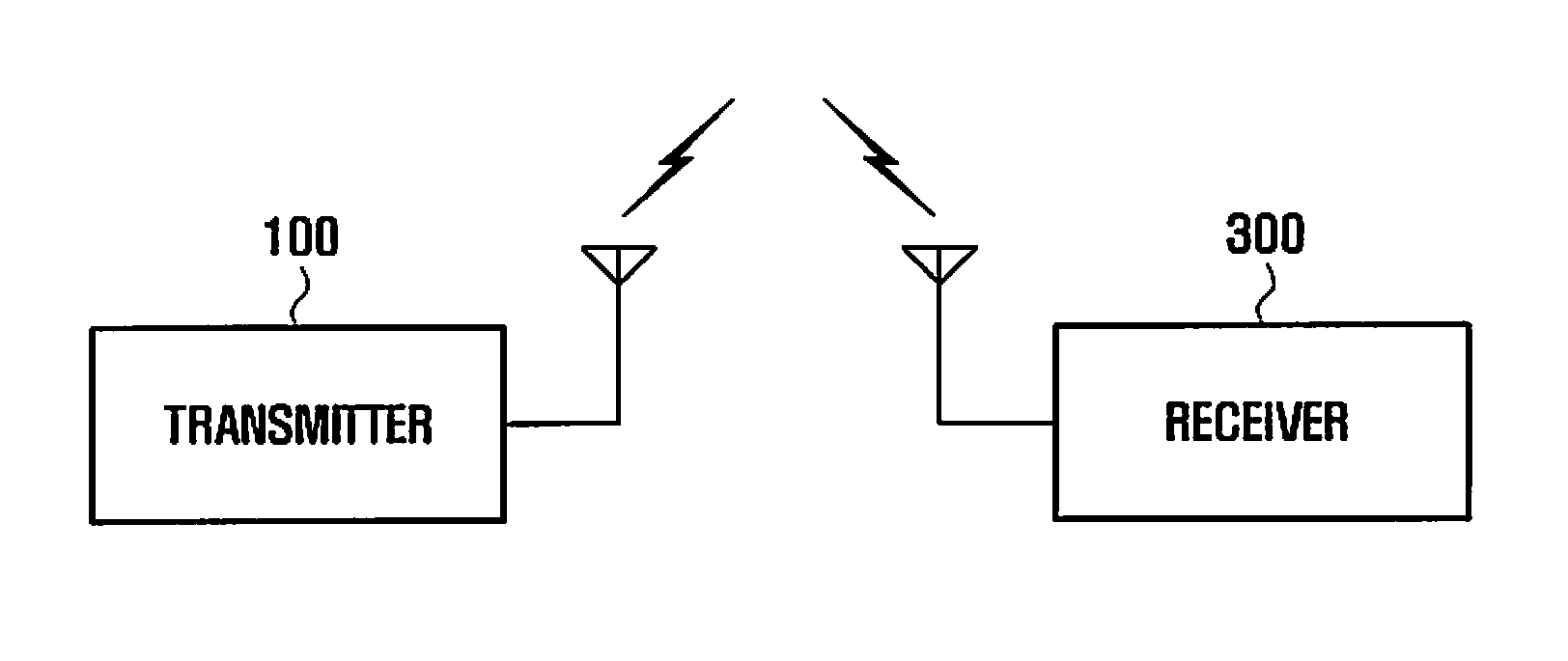
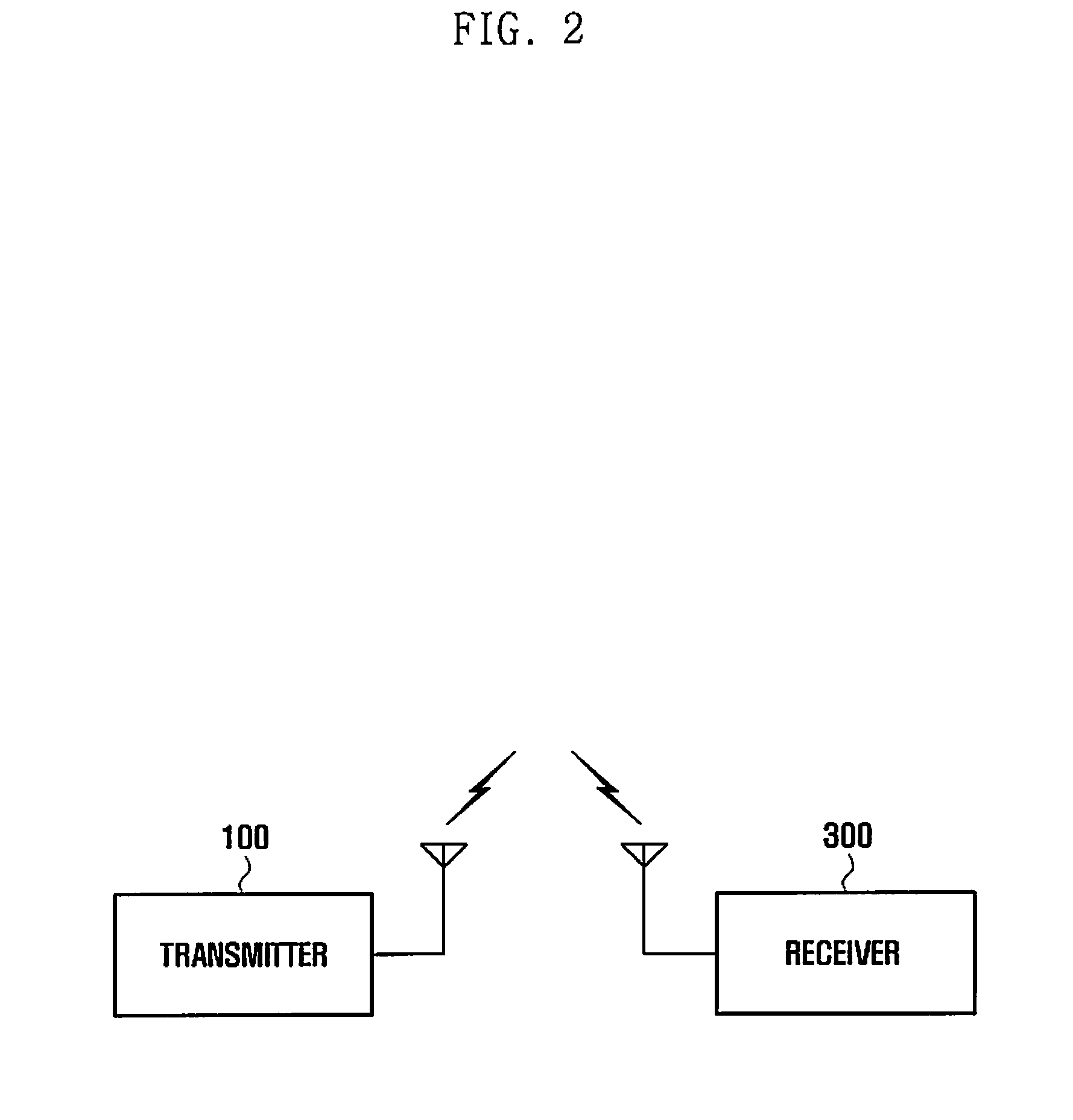
The present invention provides a wireless broadcast communication system and a broadcast service method that can provide broadcast services via a plurality of successive frames. The method includes inserting scheduling information, as inband signaling, into a serving broadcast packet, and transmitting the scheduling information via one of a plurality frames. The receiver receives the scheduling information and the target broadcast packets, and performs a control operation to receive the target broadcast packets according to the timing information. This allows for efficient and effective broadcast services in a wireless communication system.

Problems solved by technology

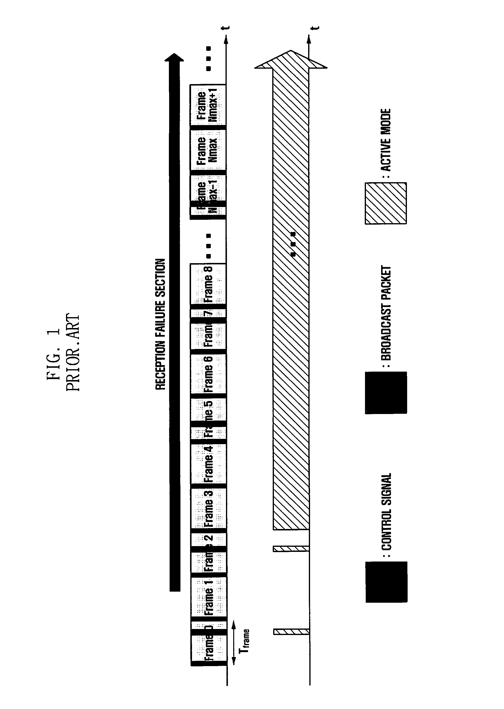
Wireless broadcast communication systems may not transmit broadcast packets at each frame with respect to the identical broadcast channel, due to the power consumption of receivers.
However, conventional wireless broadcast communication systems are disadvantageous in that they cannot efficiently use scheduling information, since it is used only to detect a particular broadcast packet in a single frame.
This is because the receiver cannot detect the position of a corresponding broadcast packet without scheduling information.
Therefore, if the receiver moves to a reception failure area, it cannot receive scheduling information transmitted by the transmitter, so that it must maintain an active mode.

Method used


Image

  • Wireless broadcast communication system and broadcast service method thereof
  • Wireless broadcast communication system and broadcast service method thereof
  • Wireless broadcast communication system and broadcast service method thereof

Examples


Embodiment Construction

[0028]Hereinafter, embodiments of the present invention are described in detail with reference to the accompanying drawings. The same reference numbers are used throughout the drawings to refer to the same or similar parts. Detailed descriptions of well-known functions and structures incorporated herein may be omitted for the sake of clarity and conciseness.

[0029]The following terms used in the present description and the claims should not be limited by a general or lexical meaning, but instead should be analyzed as a meaning and a concept through which the inventor defines and describes the present invention. Therefore, one skilled in the art will understand that the embodiments disclosed in the description and configurations illustrated in the drawings are not exhaustive, and there may be various modifications, alterations, and equivalents thereof in addition to the embodiments at the time of filing this application.

[0030]A ‘serving frame’ refers to a frame that provides a current...


PUM


Abstract

A wireless broadcast communication system includes a transmitter that provides broadcast services via a plurality of frames based on inband signaling, and a receiver that switches a sleep mode to an active mode and receives the target broadcast packets, according to the timing information. The receiver is repeatedly switched to the sleep mode according to the timing information. The system uses the scheduling information to detect broadcast packets via a plurality of frames, thereby enhancing the use efficiency of the scheduling information. Although the receiver fails to receive scheduling information via a particular frame, it can detect a position of a broadcast packet using the stored scheduling information.

Description

PRIORITY[0001]This application claims priority under 35 U.S.C. §119(a) to an application filed in the Korean Intellectual Property Office on Jun. 10, 2009 and assigned Serial No. 10-2009-0051653, the contents of which are incorporated herein by reference.BACKGROUND OF THE INVENTION[0002]1. Field of the Invention[0003]The present invention relates generally to communication systems, and more particularly, to a wireless broadcast communication system and a broadcast service method thereof that can provide broadcast services via a plurality of successive frames.[0004]2. Description of the Related Art[0005]Broadcast services generally provide digitalization, various channels, broadband, and high quality. Recently, as such devices as high definition televisions, Portable Multimedia Players (PMPs), and portable broadcast devices have proliferated, wireless broadcast communication systems have been increasingly researched and developed to provide broadcast services via various modes.[0006]...

Claims


Application Information

Patent Timeline
Patent Type & Authority Applications(United States)
IPC IPC(8): H04W40/00
CPCH04H20/426H04L47/10H04L47/14Y02D70/00H04L47/28H04W52/0216Y02D70/168H04L47/15Y02D30/70H04N7/08H04N7/12H04W8/04
Inventor LEE, IL HOLIM, YEON JUJEONG, HONG SIL
Owner SAMSUNG ELECTRONICS CO LTD
Learn More