Control rod drive mechanism for nuclear reactor

a technology of control rod and drive mechanism, which is applied in the direction of nuclear engineering, nuclear elements, greenhouse gas reduction, etc., can solve the problems of difficult structural challenges, adversely affecting the insertion precision of gray rods during normal operation, and difficulty in reattaching roller nuts to lead screws

Active Publication Date: 2010-12-16
BWXT NUCLEAR OPERATIONS GRP
View PDF12 Cites 134 Cited by
  • Summary
  • Abstract
  • Description
  • Claims
  • Application Information

AI Technical Summary

Benefits of technology

[0010]In one aspect of the disclosure, a control rod mechanism for use in a nuclear reactor, the control rod mechanism comprises: a control rod configured for insertion in a reactor core to absorb neutrons; a connecting rod connected with the control rod; a drive mechanism including a lead screw engaged with a motor-driven nut such that rotating the nut causes linear translation of the lead screw; and a latch operatively connecting the connecting rod to move together with the lead screw, the latch opening responsive to a loss or removal of electrical power to detach the connecting rod from the lead screw.
[0011]In another aspect of the disclosure, a control rod control method comprises moving a control rod linearly using a lead screw and, responsive to a scram, detaching the control rod from the lead screw whereby the control rod scrams but the lead screw does not scram.
[0012]In another aspect of the disclosure, a nuclear rea

Problems solved by technology

These disadvantages are enhanced when an internal CRDM design is chosen in which the complex electro-mechanical CDRM is internal to the high pressure and high temperature environment within the pressure vessel.
Placement of the CRDM internally within the pressure vessel also imposes difficult structural challenges.
The separable roller-nut creates a complex linkage with the lead screw that can adversely impact gray rod insertion precision during normal operation.
Reattachment of the roller-nut to the lead screw can be complex, and it may not be immediately app

Method used


Image

  • Control rod drive mechanism for nuclear reactor
  • Control rod drive mechanism for nuclear reactor
  • Control rod drive mechanism for nuclear reactor

Examples


Embodiment Construction

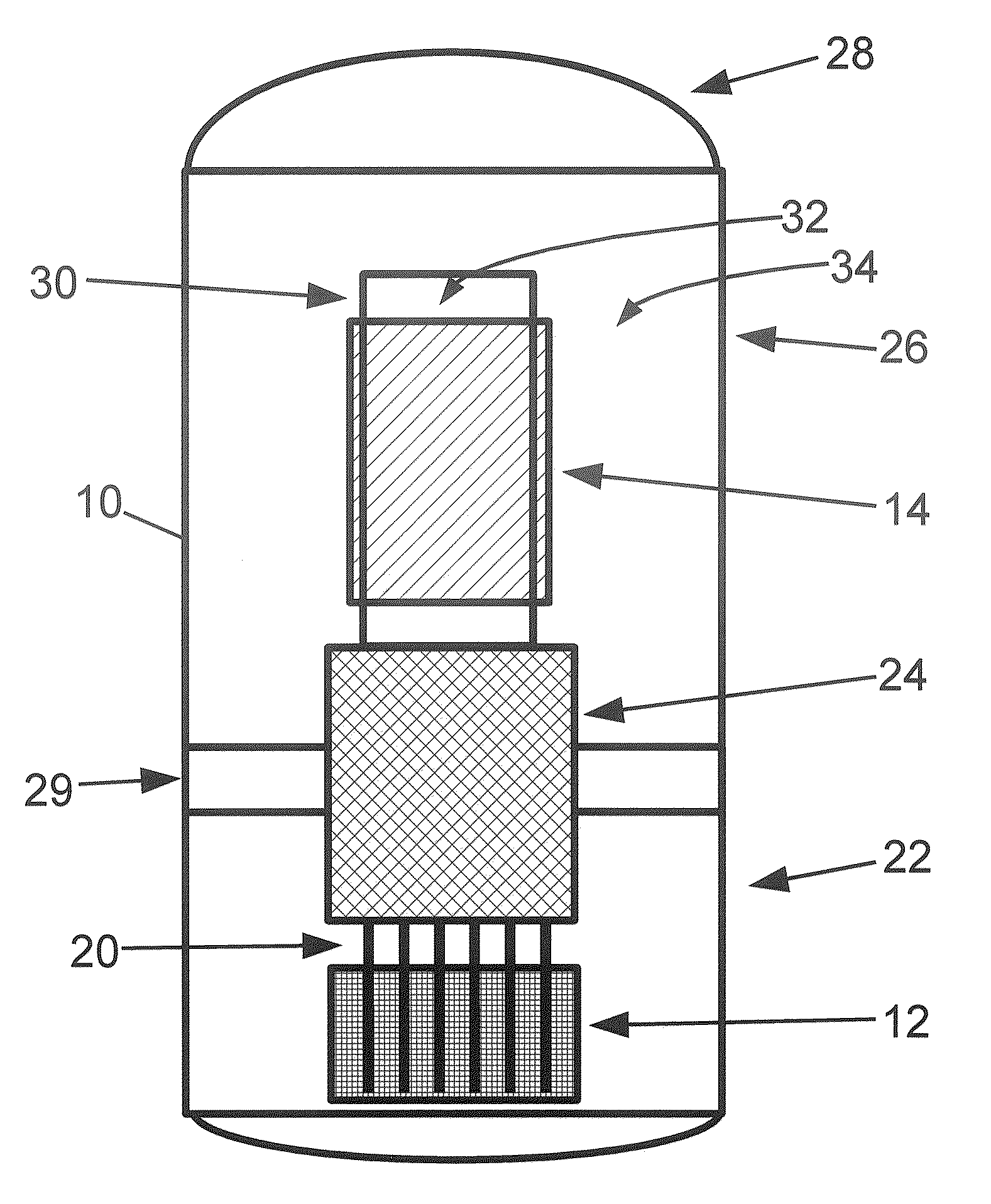
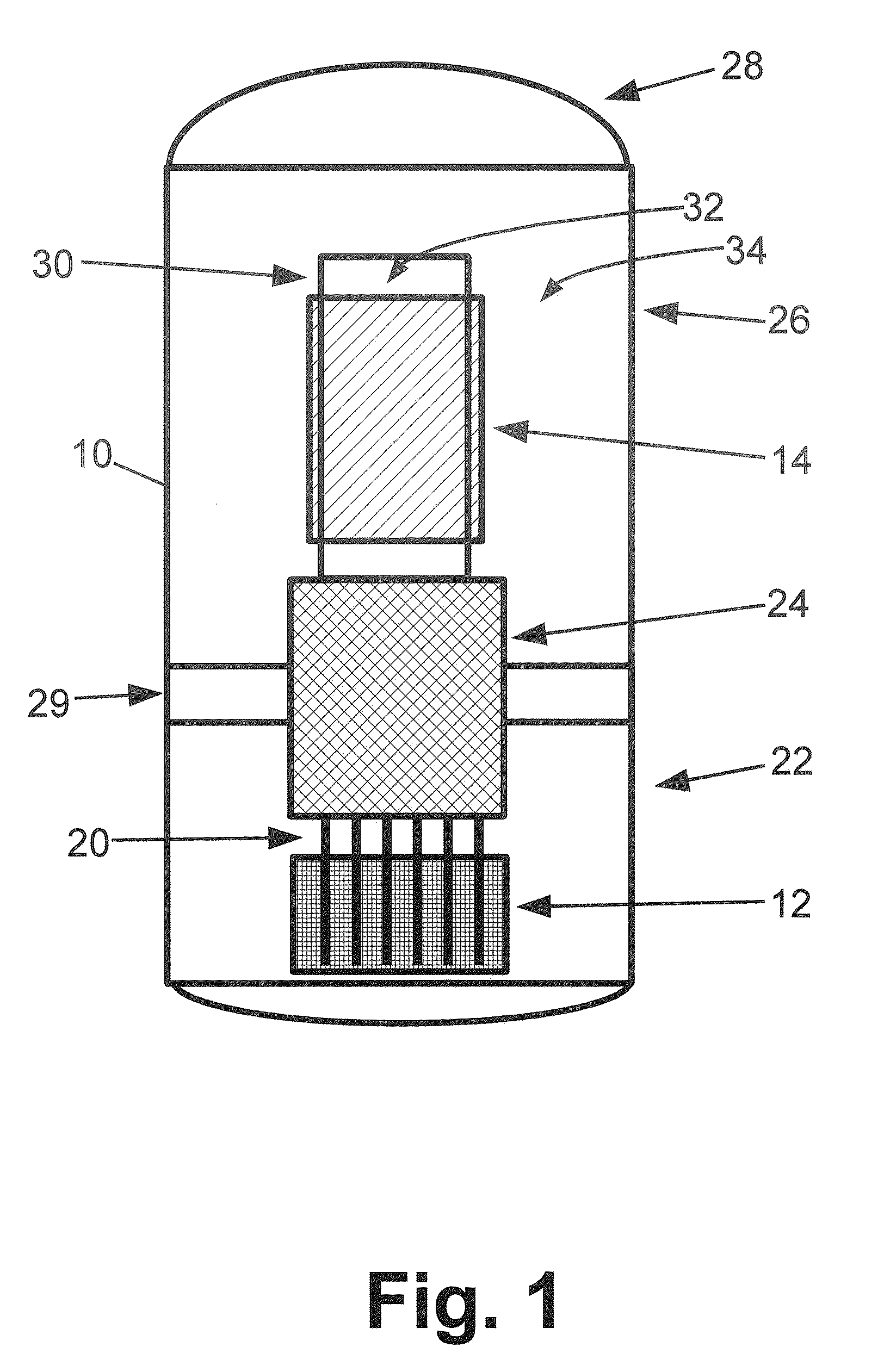
[0019]With reference to FIG. 1, an illustrative nuclear reactor vessel of the pressurized water reactor (PWR) type is diagrammatically depicted. An illustrated primary vessel 10 contains a reactor core 12, internal helical steam generators 14, and internal control rods 20. The illustrative reactor vessel includes four major components, namely: 1) a lower vessel 22, 2) upper internals 24, 3) an upper vessel 26 and 4) an upper vessel head 28. A mid-flange 29 is disposed between the lower and upper vessel sections 22, 26. Other vessel configurations are also contemplated. Note that FIG. 1 is diagrammatic and does not include details such as pressure vessel penetrations for flow of secondary coolant into and out of the steam generators, electrical penetrations for electrical components, and so forth.

[0020]The lower vessel 22 of the illustrative reactor vessel 10 of FIG. 1 contains the reactor core 12, which can have substantially any suitable configuration. One suitable configuration in...


PUM


Abstract

A control rod drive mechanism (CRDM) for use in a nuclear reactor, the CRDM comprising: a connecting rod connected with at least one control rod; a lead screw; a drive mechanism configured to linearly translate the lead screw; an electromagnet coil assembly; and a latching assembly that latches the connecting rod to the lead screw responsive to energizing the electromagnet coil assembly and unlatches the connecting rod from the lead screw responsive to deenergizing the electromagnet coil assembly. The latching assembly is secured with and linearly translates with the lead screw, while the electromagnet coil assembly does not move with the lead screw. The electromagnet coil assembly is at least coextensive with a linear translation stroke over which the drive mechanism is configured to linearly translate the lead screw.

Description

[0001]This application claims the benefit of U.S. Provisional Application No. 61 / 185,887 filed Jun. 10, 2009. U.S. Provisional Application No. 61 / 185,887 filed Jun. 10, 2009 is incorporated herein by reference in its entirety.BACKGROUND[0002]In a pressurized water reactor (PWR) or other type of nuclear reactor, movable control rods are used to control the nuclear reaction. The control rods include a neutron absorbing material, and are arranged to be inserted into the reactor core. In general, the further the control rods are inserted into the core, the more neutrons are absorbed and the more the nuclear reaction rate is slowed. Precise control of the amount of insertion, and accurate measurement of same, is useful in order to precisely control the reactivity. The control rods drive mechanism (CRDM) provides this control.[0003]In an emergency, the control rods can be fully inserted in order to quickly quench the nuclear reaction. In such a “scram”, it is useful to have an alternative...

Claims


Application Information

Patent Timeline
IPC IPC(8): G21C7/06
CPCG21C7/117Y02E30/39G21C9/02G21C7/14Y02E30/30G21C7/06
Inventor STAMBAUGH, KEVIN J.DESANTIS, PAUL K.MACKOVJAK, ALLAN R.MCLAUGHLIN, JOHN P.
Owner BWXT NUCLEAR OPERATIONS GRP
Why Eureka
Try Eureka