Development Device and Image Forming Device

a technology of development device and image forming device, which is applied in the direction of instruments, electrographic process devices, optics, etc., can solve the problems of deteriorating image quality and insufficient toner charg

Inactive Publication Date: 2010-12-16
BROTHER KOGYO KK
View PDF11 Cites 10 Cited by
  • Summary
  • Abstract
  • Description
  • Claims
  • Application Information

AI Technical Summary

Benefits of technology

[0009]Aspects of the present invention are advantageous in that they provide at least one of a development device and an image forming device configured to stably shake off a developer along a carrying path of the developer is provided.

Problems solved by technology

However, there is a case where toner not properly charged (e.g., toner not charged or the toner charged to have an inversed polarity) is mixed into the toner in the toner box.
In this case, the quality of a formed image may be deteriorated.

Method used


Image

  • Development Device and Image Forming Device
  • Development Device and Image Forming Device
  • Development Device and Image Forming Device

Examples


first embodiment

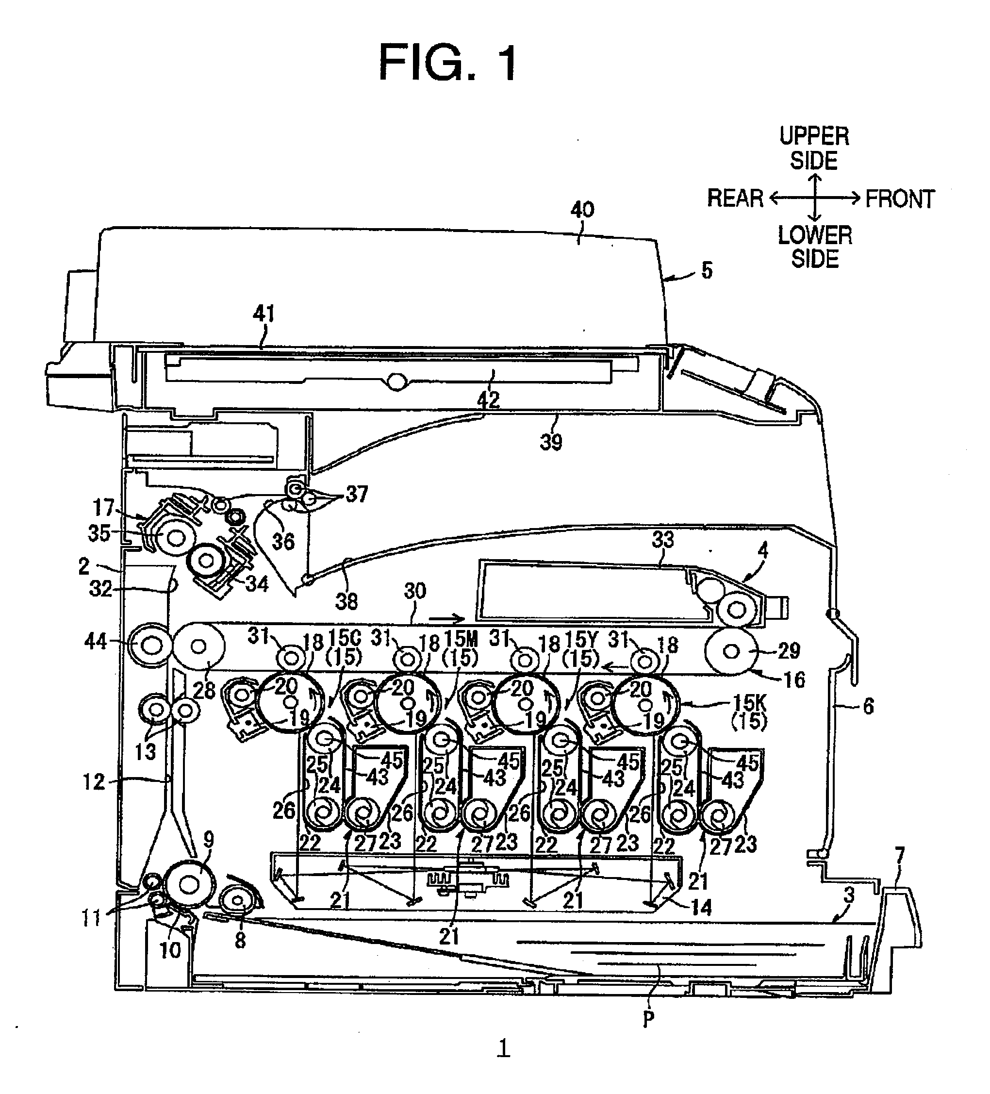
[0035]As shown in FIG. 1, a laser printer 1 according to a first embodiment is a horizontal tandem-type color laser printer. The laser printer 1 has a body casing 2 in which a paper supply unit 3 which supplies a sheet of paper P (which is an example of a recording medium, an image formation unit 4 for forming an image on a sheet of paper P, and an image reading unit 5 for reading an image from a document are accommodated. That is, the laser printer 1 is a multifunction peripheral in which the image formation unit 4 and the image reading unit 5 are integrally provided.

[0036]The body casing 2 which accommodates the paper supply unit 3, the image formation unit 4 and the image reading unit 5 has a box-shape when viewed as a side view, and is provided with a front cover 6 on one side thereof.

[0037]In the following, the side on which the front cover 6 is provided is defined as a front side, and the opposite side (i.e., the left side on the paper of FIG. 1) is defined as a rear side. The...

second embodiment

[0161]Hereafter, a laser printer 1B according to a second embodiment is described. In the following, to elements which are substantially the same as those shown in the first embodiment, same reference numbers are assigned, and explanations thereof will not be repeated for the sake of simplicity. In the following, the explanations focus on the feature of the second embodiment.

[0162]As shown in FIG. 9, the laser printer 1B according to the second embodiment has substantially the same configuration as that of the first embodiment, and includes the body casing 2, the paper supply unit 3, an image formation unit 4B and the image reading unit 5.

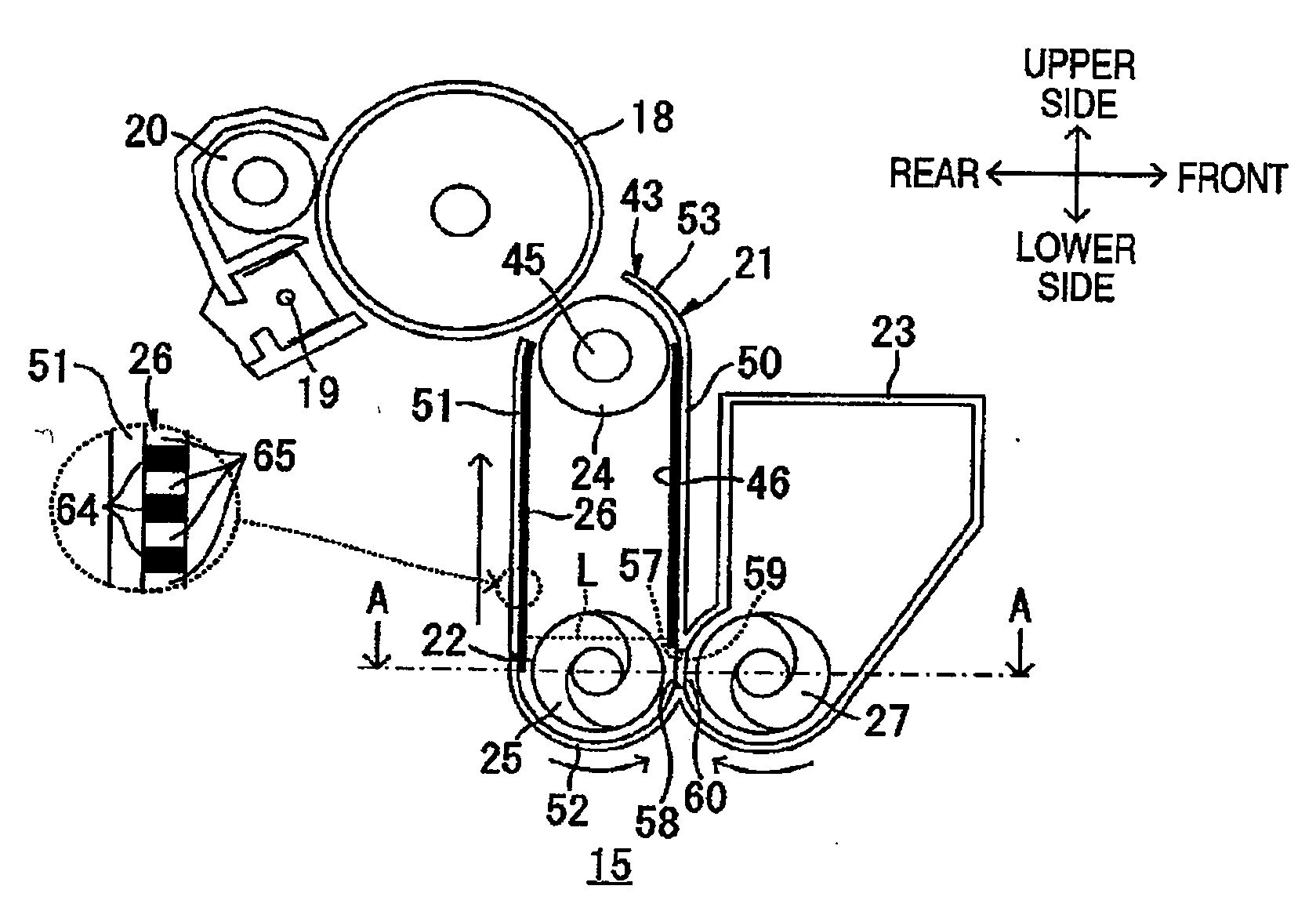
[0163]The image formation unit 4B includes the scanning unit 14, four process units 15, the transfer unit 16 and the fixing unit 17. The process units 15 are provided respectively for four colors. More specifically, the process units 15 include a black process unit 1K, an yellow process unit 15Y, a magenta process unit 15M and a cyan process unit 1...

third embodiment

[0268]Hereafter, a laser printer 1C according to a third embodiment is described. In the following, to elements which are substantially the same as those shown in the first embodiment, same reference numbers are assigned, and explanations thereof will not be repeated. In the following, the explanations focus on the feature of the third embodiment.

[0269]As shown in FIG. 16, the laser printer 1C according to the third embodiment has substantially the same configuration as that of the first embodiment, and includes the body casing 2, the paper supply unit 3, an image formation unit 4C and the image reading unit 5.

[0270]The image formation unit 4C includes the scanning unit 14, four process units 15, the transfer unit 16 and the fixing unit 17.

[0271]Under the body casing 2, the scanning unit 14 is located on the upper side of the paper supply unit 3. The scanning unit 14 emits laser beams for the four photosensitive drums 18, respectively. That is, the scanning unit 14 emits each laser ...


PUM


Abstract

A development device, comprising: a casing; a developer reservoir formed at a bottom part of the casing; a developer supply chamber that accommodates the developer; a developer holding body that is provided to be rotatable about a rotation axis extending in a width direction of the casing and is located on an upper side of the developer reservoir to face an image holding body; a first carry member that is provided in the developer supply chamber to extend in the width direction and to carry the developer to the width direction, a second carry member that is provided on a casing side to extend in the width direction and to carry the developer to the width direction; and a carry substrate that is provided in the casing so that the developer is carried from the developer reservoir to a position facing the developer holding body.

Description

CROSS-REFERENCE TO RELATED APPLICATION[0001]This application claims priority under 35 U.S.C. §119 from Japanese Patent Applications No. 2009-141452, filed on Jun. 12, 2009, No. 2009-141453, filed on Jun. 12, 2009, and No. 2009-141454, filed on Jun. 12, 2009. The entire subject matter of the applications is incorporated herein by reference.BACKGROUND[0002]1. Technical Field[0003]Aspects of the present invention relate to a development device for developing a toner image and to an image forming device in which the development device is provided.[0004]2. Related Art[0005]In general, image forming devices, such as a copying device, a printer and a facsimile device are provided with a development device for developing an electrostatic latent image formed on a photosensitive drum. As an example of a development device, a development device configured to electrostatically carry toner is widely used. More specifically, the development device includes a toner box for accommodating charged to...

Claims


Application Information

Patent Timeline
Patent Type & Authority Applications(United States)
IPC IPC(8): G03G15/08
CPCG03G15/0808G03G2215/0869
Inventor SATO, SHOUGONISHIWAKI, KENJIRO
Owner BROTHER KOGYO KK
Why Eureka
Try Eureka