Wind turbine rotor blade and airfoil section

Inactive Publication Date: 2010-12-16
HEARTLAND ENERGY SOLUTIONS
View PDF3 Cites 14 Cited by
  • Summary
  • Abstract
  • Description
  • Claims
  • Application Information

AI Technical Summary

Benefits of technology

[0012]On the other hand, if a 30% maximum thickness blade including an airfoil for operation at Reynolds numbers between about 1.1 and 1.3×10⁶ is created instead by careful design and paying careful attention to the effects of slight changes in chord length and twist on curvature, then the strength of the blade can be incr

Problems solved by technology

However, employing these programs has created problems with wind turbines.
Allowing a CAD program to loft the blade surface for airfoil sections which have been arbitrarily placed for optimal aerodynamics may result in waves or ripples in the surface loft that can be deleterious to structural integrity.
However, keeping the thickness low often results in blades that may not be able to bear the loads required; these blades may buckle.
On the other hand, incorrectly assigned airfoil coordinates for thicker blades can

Method used


Image

  • Wind turbine rotor blade and airfoil section
  • Wind turbine rotor blade and airfoil section
  • Wind turbine rotor blade and airfoil section

Examples


Example

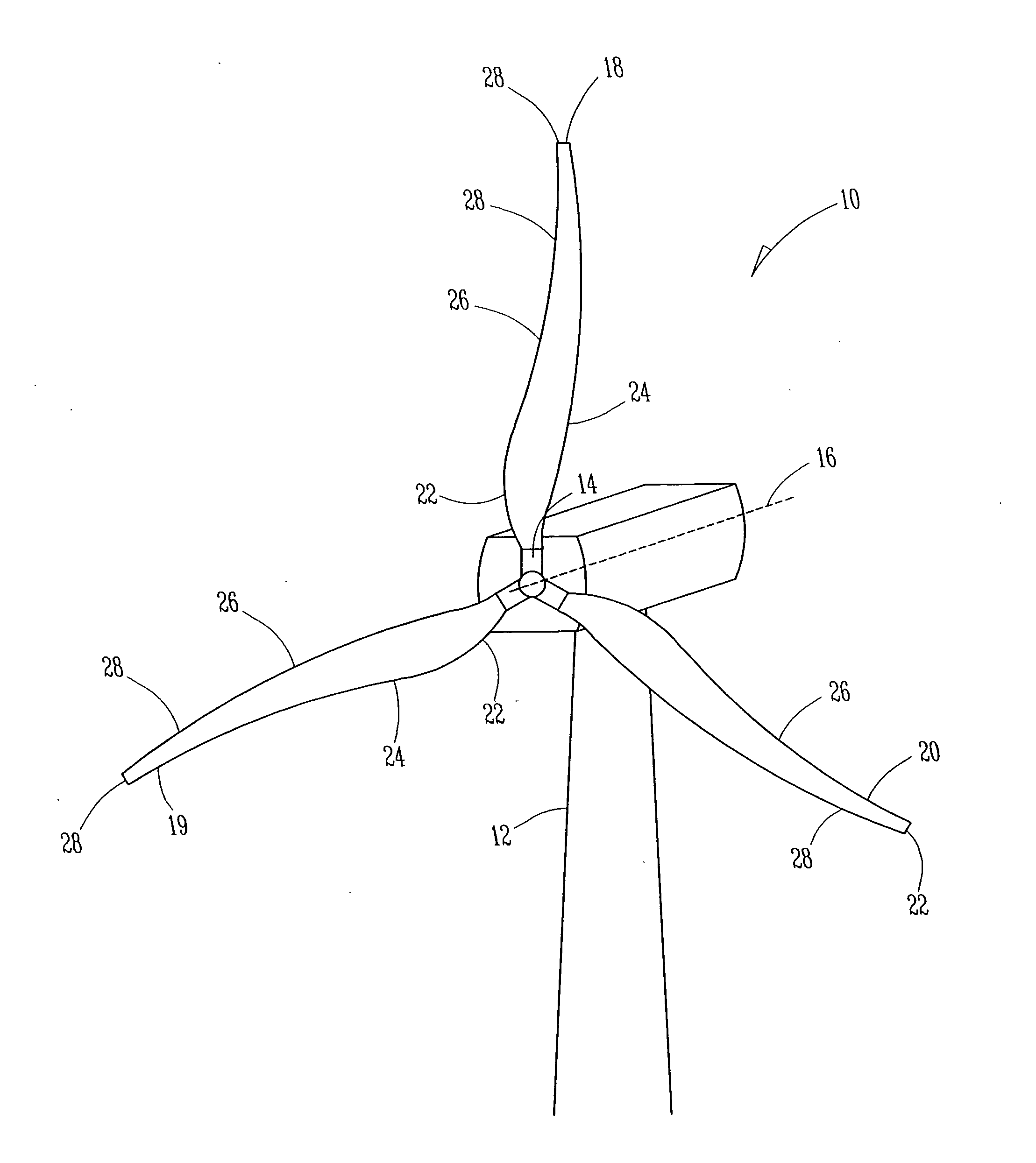
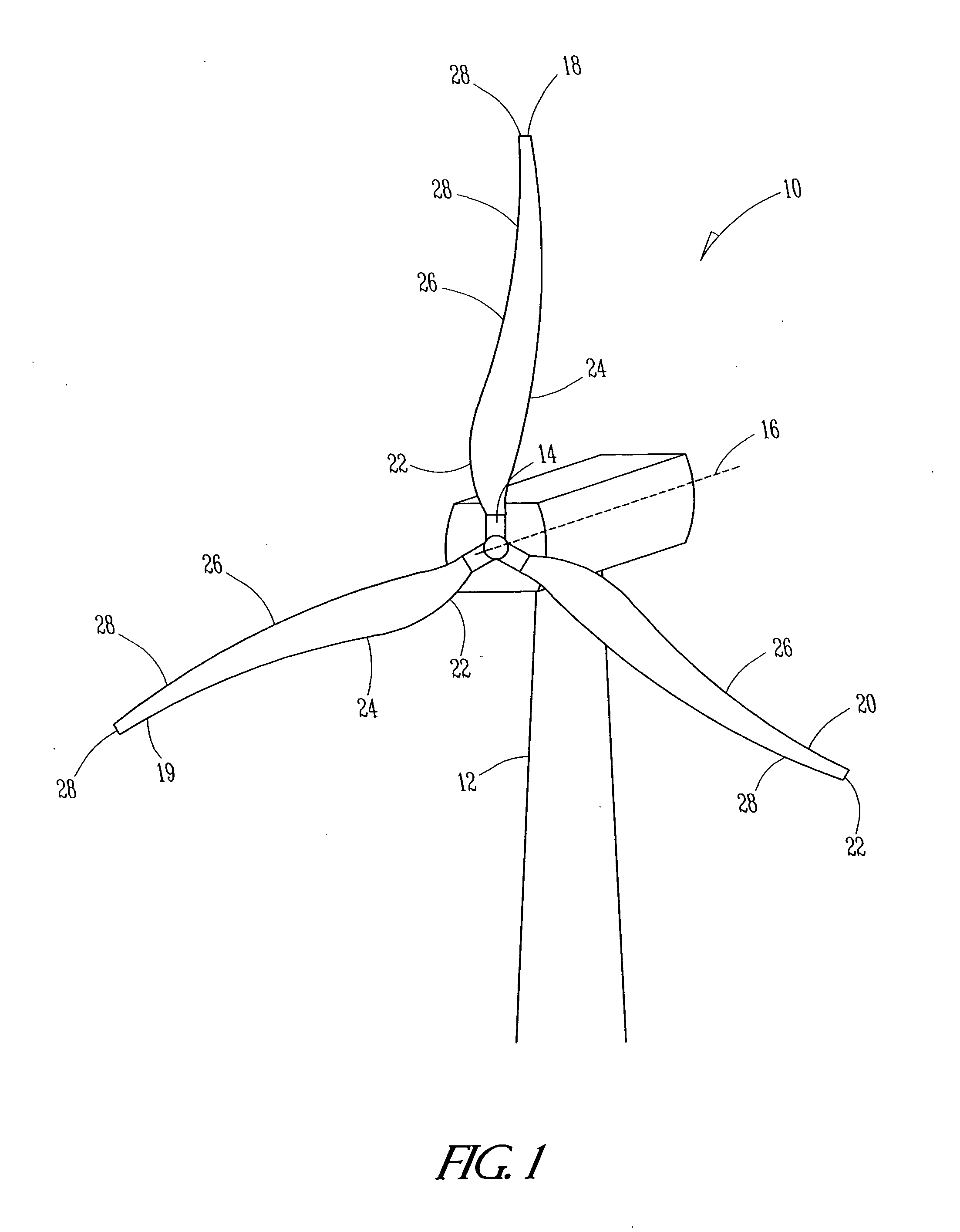
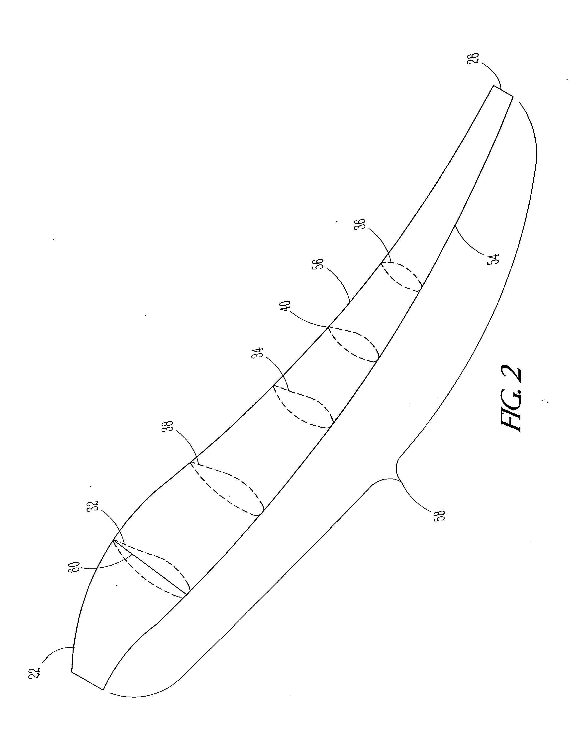
[0026]A horizontal axis wind turbine 10 having a tower 12, a hub 14, a horizontal axis 16, and a plurality of blades 18, 19 and 20 each having a root 22, a root region 24, mid-span region 26, a tip 28, and a tip 30 region each comprising at least one airfoil 32, 34, 36, 38 and 40 of the present invention is presented in FIG. 1. As also shown in FIGS. 2 and 2a, each of said plurality of blades 18, 19 and 20 further comprises an upper surface 50, a lower surface 52, the airfoils 32-40, a leading edge 54, a trailing edge 56, and a span 58 extending from root 22 to tip 28 and is further numerically characterized by a tip speed ratio. Each of said at least one airfoil 32, 34, 36, 38 and 40 comprises a chord 60 which is the distance between the leading edge 54 and the trailing edge 56, a thickness 64 perpendicular to the chordline 60 extending between the upper surface 50 and the lower surface 52 and expressed as a percentage of the chord 60, and a maximum lift coefficient and a design Re...


PUM


Abstract

The present invention includes a set of airfoils, U rails and V rails taken together to describe a blade for use with a horizontal axis wind turbine. The blade's design includes a maximum thickness higher than conventional blades employed for the same use thereby providing better load bearing structural characteristics while at the same time maintaining the requisite aerodynamic qualities for similar blades. The blade has a Reynolds number in the range of about 1.1 to 1.3×10⁶ and a maximum lift coefficient of about 1.3.

Description

FIELD OF INVENTION [0001]The present invention relates in general to rotor blades for wind turbines wherein the blade of the present invention comprises an airfoil that, in combination with designed airfoils at other stations, provides better load bearing structural characteristics than the generally acceptable blades. The blade is characterized by a family of airfoils distributed at spanwise stations at about 25%, 35%, 55%, 75% and 95% in the mid-span region and tip region. Specifically, the blade so described has a mid-span airfoil exhibiting a thickness of about 30%, a Reynolds number in the range of about 1.1×10⁶ to 1.3×10⁶ and a maximum lift coefficient of about 1.3.BACKGROUND [0002]Wind turbines operate at either a constant rotational speed or at variable rotational speeds that are proportional to the wind velocity. Peak power at high wind speeds is usually controlled through stall regulation or through the use of variable pitch turbine blades. A conventional horizontal axis w...

Claims


Application Information

Patent Timeline
IPC IPC(8): F03D1/06F03D11/00
CPCF03D1/0641F05B2240/301Y02E10/721Y02E10/72
Inventor BLANTON, JEFFREY TODDPRESTON, LARRY DUANE
Owner HEARTLAND ENERGY SOLUTIONS
Why Eureka
Try Eureka