Base station apparatus and interference reducing method

a base station and interference reduction technology, applied in the field of mobile radio communication technologies, can solve the problems of weak interference in adjacent cells, inability to specify the same radio wave reaching range in some cases, and inability to achieve transmission diversity gain, so as to reduce interference in adjacent cells and increase the throughput of all terminals

Inactive Publication Date: 2010-12-16
HITACHI LTD
View PDF5 Cites 27 Cited by
  • Summary
  • Abstract
  • Description
  • Claims
  • Application Information

AI Technical Summary

Benefits of technology

[0027]According to the present invention, it is possible to control inter-cell interference according to the state and position of each radio terminal.
[0028]According to the present invention, it is possible, when a plurality of transmission antennas provided for a base station apparatus have different radio wave reaching regions, to reduce interference in adjacent cells while the signal-to-noise ratio (SNR) at the position of a terminal is maintained at a value close to that obtained when transmission diversity is applied. According to the present invention, it is possible to increase the throughput of all terminals disposed in the area where the terminals are located.

Problems solved by technology

In actual operation, however, when an antenna is shared by a plurality of systems, the same radio wave reaching range cannot be specified in some cases.
In addition, an antenna having a wide radio wave reaching range causes strong interference in adjacent cells.
If a plurality of antennas have different propagation lengths, the transmission diversity gain is not obtained and interference occurs in an adjacent area.

Method used


Image

  • Base station apparatus and interference reducing method
  • Base station apparatus and interference reducing method
  • Base station apparatus and interference reducing method

Examples


Embodiment Construction

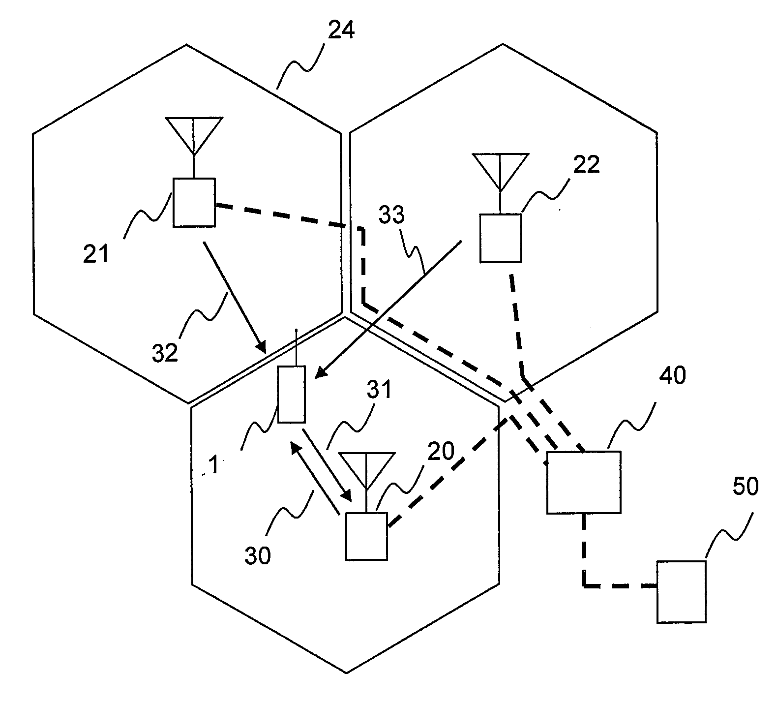
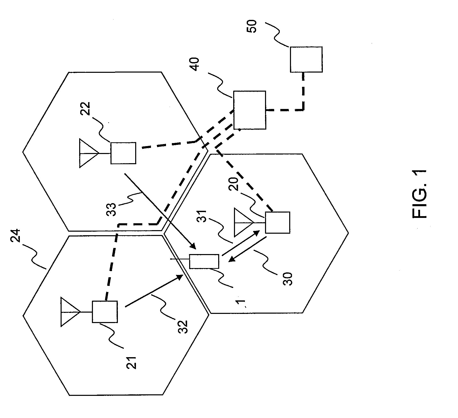
[0044]FIG. 1 is a view showing an example structure of a mobile communication system (or a radio communication system).

[0045]Base station apparatuses (hereinafter called just base stations sometimes) 20 to 22 communicate with a core apparatus 50 to connect to a core network through the core apparatus 50. A signal sent from the core apparatus 50 is input to the base station apparatus 20 through a switch 40. The base station apparatus 20 converts the signal sent from the core apparatus to a high frequency signal and sends it to a mobile terminal (or a radio terminal) 1 by a radio signal 30. The mobile terminal 1 receives the radio signal 30 sent from the base station apparatus 20 and performs signal processing to convert the radio signal 30 to information, thereby communicating with the core apparatus 50.

[0046]The mobile terminal 1 converts information generated therein to a high frequency signal and sends it to the base station apparatus 20 by a radio signal 31. The radio signal sent...


PUM


Abstract

A base station has a first antenna for emitting radio waves at a first tilt angle and a second antenna for emitting radio waves at a second tilt angle different from the first tilt angle. If the antennas have different propagation lengths, a transmission diversity gain is not obtained and interference occurs in an adjacent area. In such a case, when one antenna having a shorter propagation length, which means less interference in the adjacent area, is used for transmission, the throughput of each terminal is increased at the area. For example, a controller changes two antenna transmission to one antenna transmission when the difference between the reception qualities of signals sent from the base station and an adjacent base station adjacent to the base station is smaller than a predetermined reference, the reception qualities being measured at the terminal.

Description

CLAIM OF PRIORITY[0001]The present application claims priority from Japanese patent application JP 2009-140755 filed on Jun. 12, 2009, the content of which is hereby incorporated by reference into this application.BACKGROUND OF THE INVENTION[0002]1. Field of the Invention[0003]The present invention relates to mobile radio communication technologies, and more particularly, to a technology for reducing interference between frequencies close to each other at a cell boundary or a sector boundary of a base station having a plurality of transmission antennas in a mobile radio communication system employing the orthogonal frequency division multiple access (OFDMA) method.[0004]2. Description of the Related Art[0005]A mobile radio communication system is formed of a plurality of base station apparatuses and a plurality of mobile terminals (or radio terminals) communicating in radio with the plurality of base station apparatuses. The plurality of base station apparatuses are disposed separat...

Claims


Application Information

Patent Timeline
Patent Type & Authority Applications(United States)
IPC IPC(8): H04B15/00
CPCH04W72/085H04W72/046H04W72/542
Inventor TAKATANI, KENJIROYAGISAWA, KENICHI
Owner HITACHI LTD
Why Eureka
Try Eureka