Range finder
- Summary
- Abstract
- Description
- Claims
- Application Information
AI Technical Summary
Benefits of technology
Problems solved by technology
Method used
Image
Examples
first embodiment
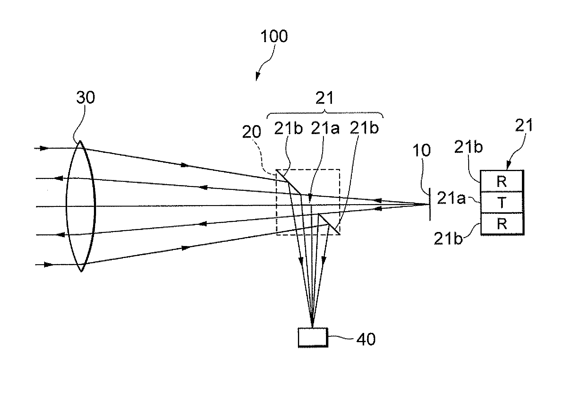
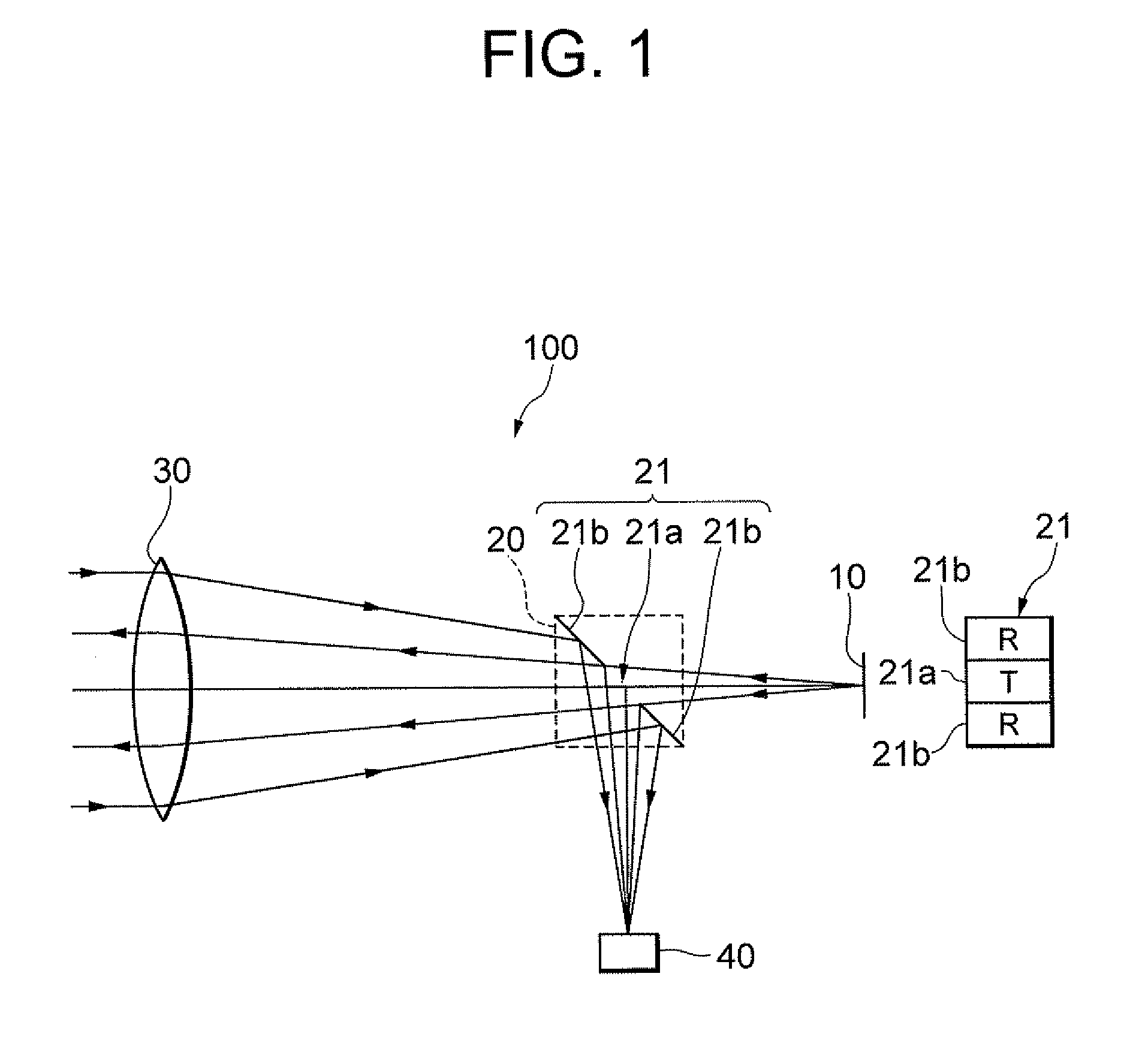
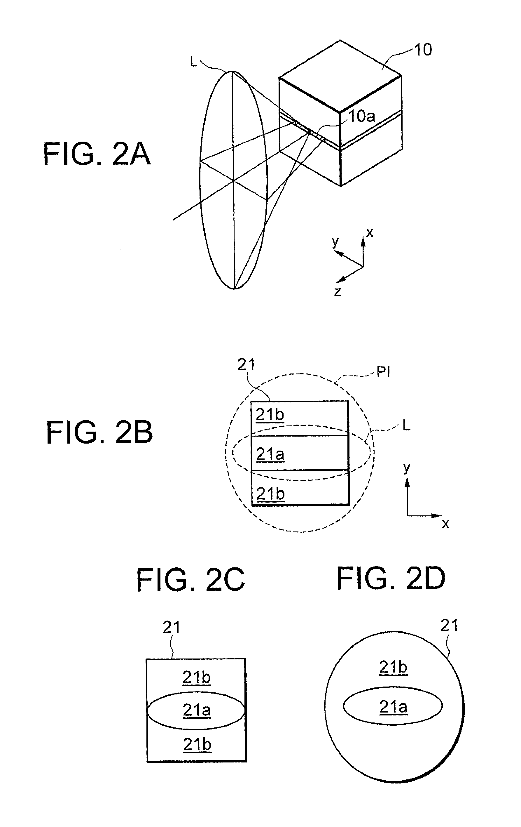
[0022]Preferred embodiments according to the present invention are explained below with reference to accompanying drawings. A configuration of a laser range finder 100 as a distance measuring apparatus according to the first embodiment is explained with reference to FIG. 1. The laser range finder 100 is composed of a light source 10 that is a semiconductor laser, a partial reflection member 20, an objective lens 30, and a photodetector 40. The light source 10 is disposed on the focal point of the objective lens 30 or in the vicinity thereof. The partial reflection member 20 has a partial reflection surface 21 inclined with respect to an optical axis and is disposed between the light source 10 and the objective lens 30. The partial reflection surface 21 is divided into three areas, and composed of a transmitting area 21a disposed with including the optical axis and having a substantially rectangular shape, and two receiving areas 21b disposed above and below of the transmitting area,...
second embodiment
[0026]As seen in a laser range finder 200 as a distance measuring apparatus according to a second embodiment shown in FIG. 3, a partial reflection surface 21 formed on a partial reflection member 20 may be constructed by making a transmitting area 21a as a light reflection surface (R), and two receiving areas 21b as light transmission surfaces (T). In this case, measurement light emitted from a light source 10 is reflected by the transmitting area 21a formed at the center of the partial reflection surface 21, incident on an objective lens 30, transformed into substantially parallel light by the objective lens 30, and projected to an unillustrated target object. A portion of reflection light reflected and dispersed by the target object is incident on the objective lens 30, and converged by the objective lens 30 to form an image on a photodetector 40 through receiving areas 21b formed on the partial reflection surface 21. In such construction also, arrangement of the light source 10 (...
third embodiment
[0028]Then, a laser rang finder 300 as a distance measuring apparatus according to a third embodiment, which has the laser range finder 100 according to the first embodiment as a fundamental construction, is explained with reference to FIG. 4. The laser range finder 300 includes, in order from an object side, an objective lens 30, a prism member 50, a protection filter 60, a liquid crystal display 70, and an eyepiece 80. On optical paths separated by the prism member 50, a partial reflection surface 21, a condenser lens 11, a light source 10, a background-light-blocking filter 41, and a photodetector 40 are disposed. The prism member 50 is composed of a first prism 51 and a second prism 52 composing an erecting prism that converts an inverted image of the object (target object) formed by the objective lens 30 into an erect image, a third prism 53 that is cemented with the first prism 51 and forms a wavelength-separation surface 55a on the cemented surface therebetween that separates...
PUM
 Abstract
Description
Claims
Application Information
 - R&D
- Intellectual Property
- Life Sciences
- Materials
- Tech Scout
- Unparalleled Data Quality
- Higher Quality Content
- 60% Fewer Hallucinations
Browse by: Latest US Patents, China's latest patents, Technical Efficacy Thesaurus, Application Domain, Technology Topic, Popular Technical Reports.
© 2025 PatSnap. All rights reserved.Legal|Privacy policy|Modern Slavery Act Transparency Statement|Sitemap|About US| Contact US: help@patsnap.com


