Range finder

a range finder and distance measurement technology, applied in distance measurement, height/levelling measurement, instruments, etc., can solve the problems of insufficient measurement light amount, inability to secure sufficient measurement light amount, and inability to make the distance completely independent, etc., to achieve the effect of longer measuring distance and higher measuring accuracy

Inactive Publication Date: 2014-01-28
NIKON VISION
View PDF25 Cites 5 Cited by
  • Summary
  • Abstract
  • Description
  • Claims
  • Application Information

AI Technical Summary

Benefits of technology

[0013]The present invention is made in view of the above-described problem, and has an object to provide a distance measuring apparatus or range finder capable of accomplishing compactness, a longer measuring distance and higher measuring accuracy with respect to a conventional one.
[0024]In the third aspect of the present invention, it is preferable that the collimating optical system includes an eyepiece that makes it possible to observe an image formed by the objective lens.
[0027]With configuring the distance measuring apparatus or range finder as described above, it becomes possible to accomplish compactness, a longer measuring distance and higher measuring accuracy.

Problems solved by technology

However, the conventional laser range finder that makes the transmitting optical system and the receiving optical system completely independent has been disadvantageous for making it compact.
Although it has been technically possible to make it compact by making the transmitting optical system and the receiving optical system common, sufficient measurement light amount has not been secured and it has been difficult to make the measuring distance longer.
Moreover, with configuring the distance measuring apparatus or range finder as described above, since the transmitting optical path and the receiving optical path are disposed close together, a portion of light emitted from the light source is mixed into the optical path of the receiving optical system inside of the range finder to produce noise, so that S / N ratio becomes lowered and distance measurement accuracy becomes lowered.

Method used


Image

  • Range finder
  • Range finder
  • Range finder

Examples


first embodiment

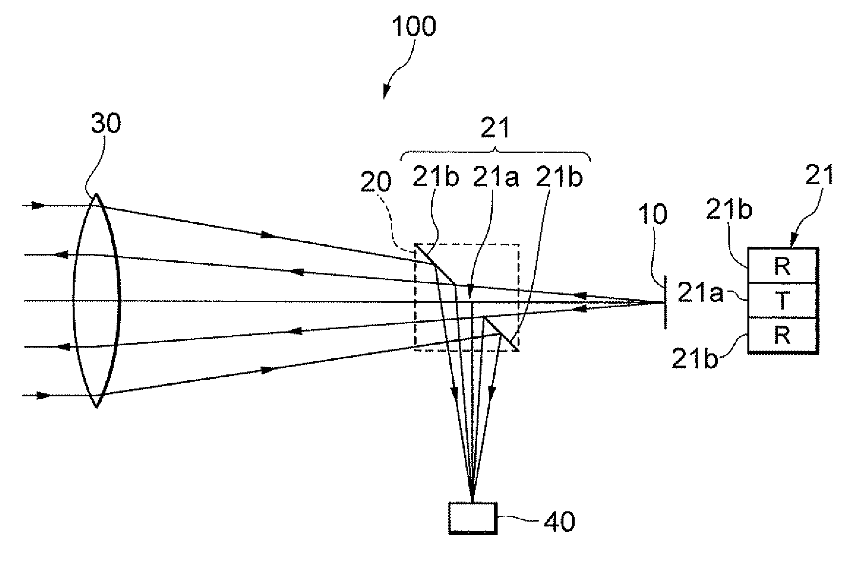
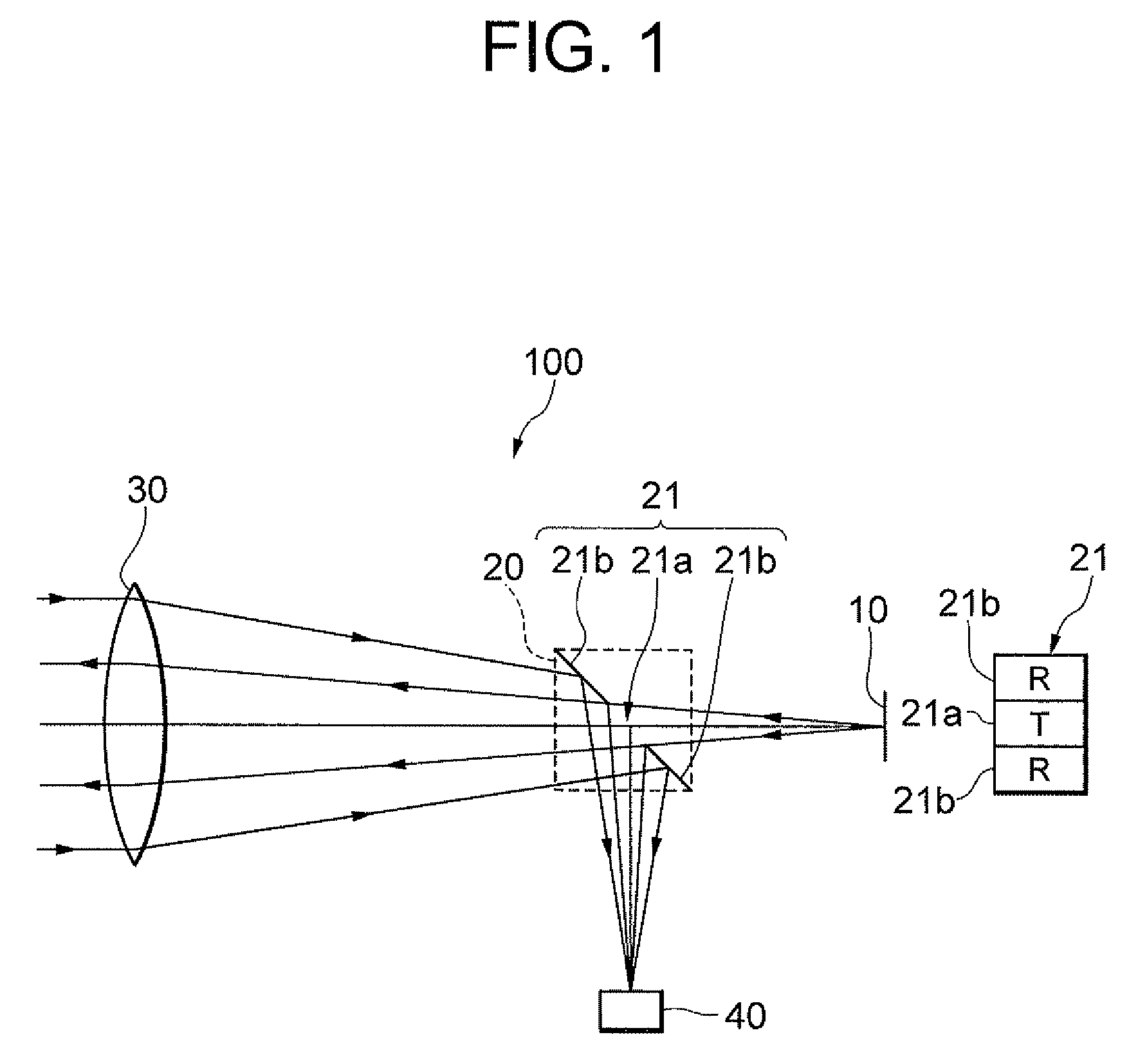
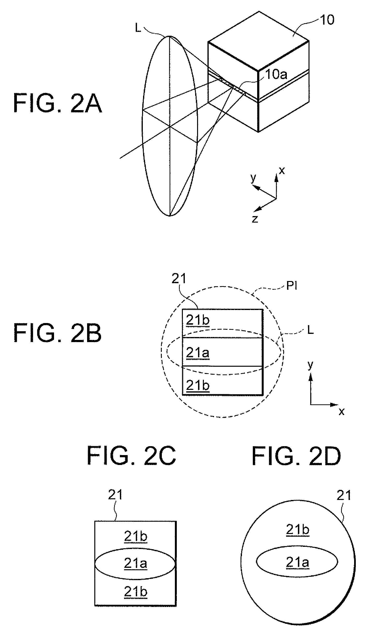
[0036]Preferred embodiments according to the present invention are explained below with reference to accompanying drawings. A configuration of a laser range finder 100 as a distance measuring apparatus according to the first embodiment is explained with reference to FIG. 1. The laser range finder 100 is composed of a light source 10 that is a semiconductor laser, a partial reflection member 20, an objective lens 30, and a photodetector 40. The light source 10 is disposed on the focal point of the objective lens 30 or in the vicinity thereof. The partial reflection member 20 has a partial reflection surface 21 inclined with respect to an optical axis and is disposed between the light source 10 and the objective lens 30. The partial reflection surface 21 is divided into three areas, and composed of a transmitting area 21a disposed with including the optical axis and having a substantially rectangular shape, and two receiving areas 21b disposed above and below of the transmitting area,...

second embodiment

[0040]As seen in a laser range finder 200 as a distance measuring apparatus according to a′second embodiment shown in FIG. 3, a partial reflection surface 21 formed on a partial reflection member 20 may be constructed by making a transmitting area 21a as a light reflection surface (R), and two receiving areas 21b as light transmission surfaces (T). In this case, measurement light emitted from a light source 10 is reflected by the transmitting area 21a formed at the center of the partial reflection surface 21, incident on an objective lens 30, transformed into substantially parallel light by the objective lens 30, and projected to an unillustrated target object. A portion of reflection light reflected and dispersed by the target object is incident on the objective lens 30, and converged by the objective lens 30 to form an image on a photodetector 40 through receiving areas 21b formed on the partial reflection surface 21. In such construction also, arrangement of the light source 10 (...

third embodiment

[0042]Then, a laser range finder 300 as a distance measuring apparatus according to a third embodiment, which has the laser range finder 100 according to the first embodiment as a fundamental construction, is explained with reference to FIG. 4. The laser range finder 300 includes, in order from an object side, an objective lens 30, a prism member 50, a protection filter 60, a liquid crystal display 70, and an eyepiece 80. On optical paths separated by the prism member 50, a partial reflection surface 21, a condenser lens 11, a light source 10, a background-light-blocking filter 41, and a photodetector 40 are disposed. The prism member 50 is composed of a first prism 51 and a second prism 52 composing an erecting prism that converts an inverted image of the object (target object) formed by the objective lens 30 into an erect image, a third prism 53 that is cemented with the first prism 51 and forms a wavelength-separation surface 55a on the cemented surface therebetween that separate...


PUM


Abstract

A laser range finder includes: a light source emitting light from a linear light-emitting portion with making a divergent angle of the light larger in a transversal direction of the light-emitting portion than in a longitudinal direction thereof; an objective lens projecting the light onto a target object and converging reflection light; a partial reflection member disposed between the light source and the objective lens and having a partial reflection surface composed of a transmitting area transmitting light emitted from the light source and receiving areas reflecting reflection light; and a photodetector detecting the reflection light reflected by the receiving areas; wherein the light source and the partial reflection member are disposed with making the longitudinal direction of the light-emitting portion disposed substantially perpendicular to a longitudinal direction of the transmitting area as seen along an optical axis.

Description

[0001]This is a Continuation-in-Part of U.S. application Ser. No. 12 / 813,006 filed Jun. 10, 2010 now U.S. Pat. No. 8,477,290. The disclosure of the prior application is hereby incorporated by reference herein in its entirety.[0002]The disclosure of the following priority applications are herein incorporated by reference:[0003]Japanese Patent Application No. 2009-147299 filed on Jun. 22, 2009,[0004]Japanese Patent Application No. 2010-007799 filed on Jan. 18, 2010, and[0005]Japanese Patent Application No. 2010-247346 filed on Nov. 4, 2010BACKGROUND OF THE INVENTION[0006]1. Field of the Invention[0007]The present invention relates to a distance measuring apparatus, or range finder.[0008]2. Related Background Art[0009]As a conventional distance measuring apparatus or range finder, there has been proposed a one that disposes a transmitting optical system and a receiving optical system completely independently (for example, see Japanese Patent Application Laid-Open No. 2002-350543).[0010...

Claims


Application Information

Patent Timeline
Patent Type & Authority Patents(United States)
IPC IPC(8): G01C3/08
CPCG01S7/4812G01C3/08G01C15/002
Inventor YAMADA, KENJI
Owner NIKON VISION
Why Eureka
Try Eureka