Bearing apparatus, spindle motor, and disk drive apparatus

a technology of disk drive and bearing, which is applied in the direction of sliding contact bearings, recording information storage, instruments, etc., can solve the problems of difficult to achieve a sufficient supporting force between the shaft and the sleeve, the failure of the dynamic pressure to be successfully generated in the lubricating fluid, and the deterioration of the rotational performance of the bearing using the lubricating fluid

Active Publication Date: 2010-12-23
NIDEC CORP
View PDF29 Cites 36 Cited by
  • Summary
  • Abstract
  • Description
  • Claims
  • Application Information

AI Technical Summary

Problems solved by technology

However, such a bearing apparatus using the lubricating fluid will deteriorate in rotational performance if air bubbles enter into the lubricating fluid so that the air bubbles are accumulated in the gap between the shaft and the sleeve.
In the case where grooves are defined in the shaft or the sleeve to generate a dynamic pressure, in particular, air bubbles may become accumulated in the vicinity of the grooves so as to make it difficult for the dynamic pressure to be successfully generated in the lubricating fluid.
This makes it difficult to achieve a sufficient supporting force between the shaft and the sleeve.

Method used


Image

  • Bearing apparatus, spindle motor, and disk drive apparatus
  • Bearing apparatus, spindle motor, and disk drive apparatus
  • Bearing apparatus, spindle motor, and disk drive apparatus

Examples


Embodiment Construction

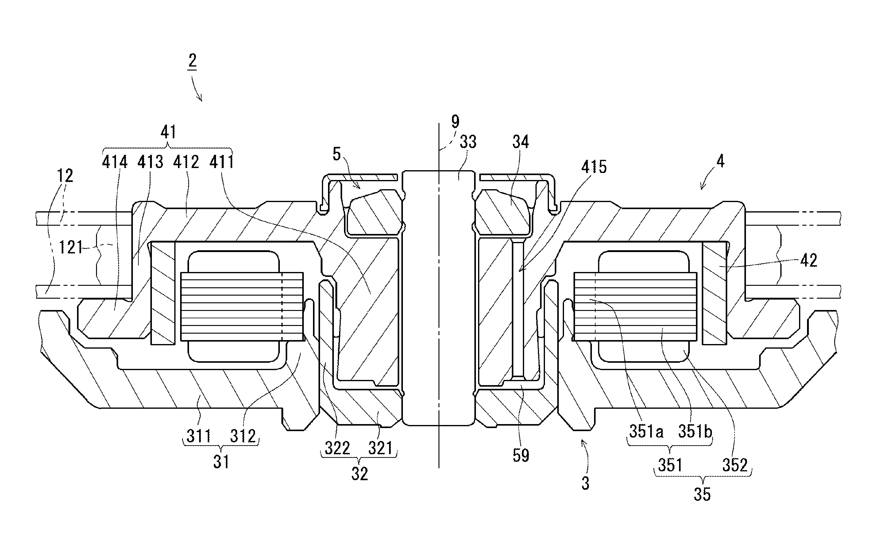
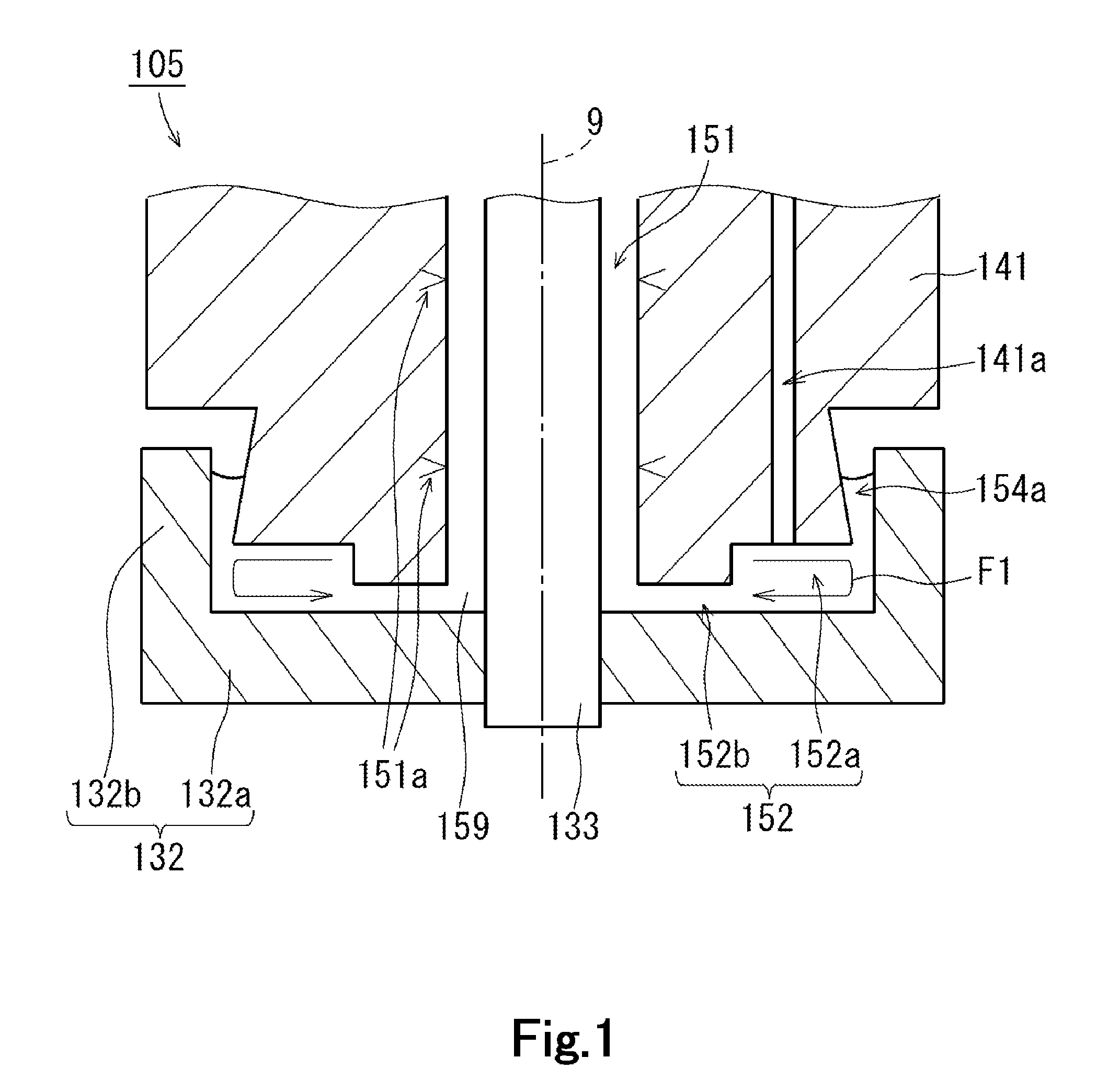
[0029]Hereinafter, preferred embodiments of the present invention will be described with reference to the accompanying drawings. A cup-shaped thrust member will be herein referred to as a “thrust cup”. It is assumed herein that an upward / downward direction is defined along a central axis 9, and that a side on which a rotating member 141 or a hub 41 is arranged relative to a thrust cup 132 or 32 is defined as an upper side. The shape of each member and relative positions of different members will be described based on this assumption. It should be noted, however, that this definition of the upper / lower or upward / downward directions is simply applied to facilitate the description provided herein, and should not be construed to restrict in any way the orientation of a bearing apparatus, a spindle motor, or a disk drive apparatus according to any preferred embodiment of the present invention when actually installed in a device.

[0030]FIG. 1 is a diagram illustrating the structure of a be...


PUM

PropertyMeasurementUnit
dynamic pressureaaaaaaaaaa
axial dimensionaaaaaaaaaa
hardnessaaaaaaaaaa

Abstract

A bearing apparatus includes a shaft, a thrust cup including an annular potion and a cylindrical portion, a rotating member including a through hole defined therein, and a lubricating oil. A second gap defined between a lower surface of the rotating member and an upper surface of the annular portion of the thrust cup includes a first region in communication with a capillary seal portion, and a second region positioned radially inward of the first region and having an axial dimension smaller than that of the first region. A lower end portion of the through hole is open at a location radially outwardly away from a boundary between the first and second regions, so that a local circulation of the lubricating oil arises within the first region during rotation of the rotating member.

Description

BACKGROUND OF THE INVENTION[0001]1. Field of the Invention[0002]The present invention relates to a bearing apparatus, a spindle motor, and a disk drive apparatus.[0003]2. Description of the Related Art[0004]Hard disk apparatuses and optical disk apparatuses are typically provided with a spindle motor arranged to rotate a disk or disks about a central axis thereof. The spindle motor includes a stationary portion fixed to a housing of the apparatus, and a rotating portion arranged to rotate while supporting the disk(s). The spindle motor is arranged to produce a torque centered on the central axis by magnetic flux generated between the stationary and rotating portions, whereby the rotating portion is caused to rotate with respect to the stationary portion.[0005]The stationary and rotating portions of the spindle motor are joined to each other through a bearing apparatus. In recent years, in particular, spindle motors have often been provided with a bearing apparatus in which a lubrica...

Claims


Application Information

Patent Timeline
Patent Type & Authority Applications(United States)
IPC IPC(8): G11B5/127F16C32/06H02K7/08
CPCF16C33/103F16C33/107F16C17/107G11B19/2036F16C2370/12F16C33/745
Inventor OE, TAKAYUKIHIRONO, TEIICHISAKURADA, KUNIOMIZUKAMI, JUNYA
Owner NIDEC CORP
Why Eureka
Try Eureka