Eureka AIR delivers breakthrough ideas for toughest innovation challenges, trusted by R&D personnel around the world.

Temperature Compensation Element for a Connection Unit

Inactive Publication Date: 2010-12-23
SIEMENS AG
View PDF4 Cites 1 Cited by
  • Summary
  • Abstract
  • Description
  • Claims
  • Application Information

AI Technical Summary

Benefits of technology

[0004]The object of the present invention is to create a temperature compensation element for a connection unit of the type mentioned at the start of this document which minimizes a temperature gradient at the connection terminals of the connection unit.
[0008]A further embodiment of the invention makes it possible to manufacture the temperature compensation element using simple methods. To manufacture two interconnected strips a right-angled copper plate which is appropriately folded is sufficient.

Problems solved by technology

This leads to imprecise temperature measurements, in particularly because the connection terminals are subjected to different thermal influences by components of the circuit board of the module.

Method used


Image

  • Temperature Compensation Element for a Connection Unit
  • Temperature Compensation Element for a Connection Unit

Examples


Embodiment Construction

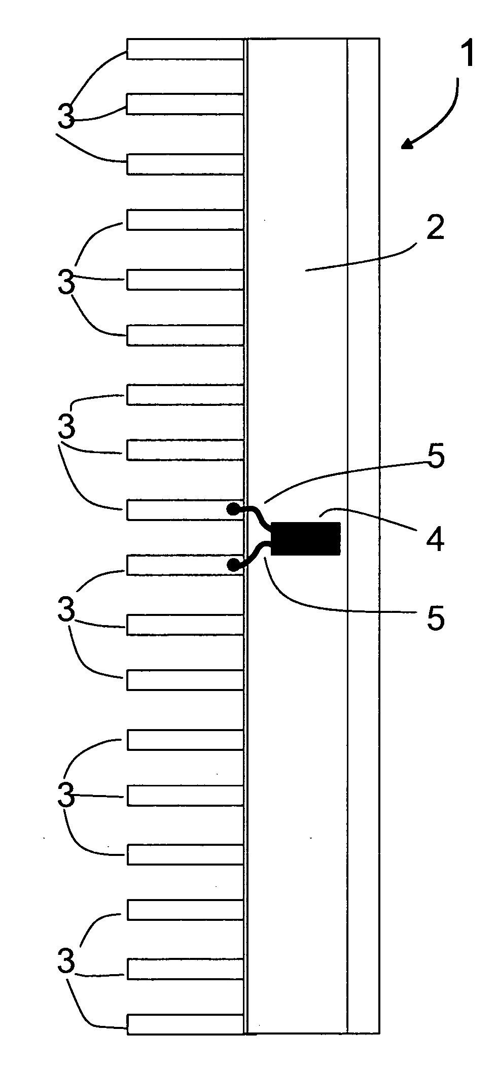
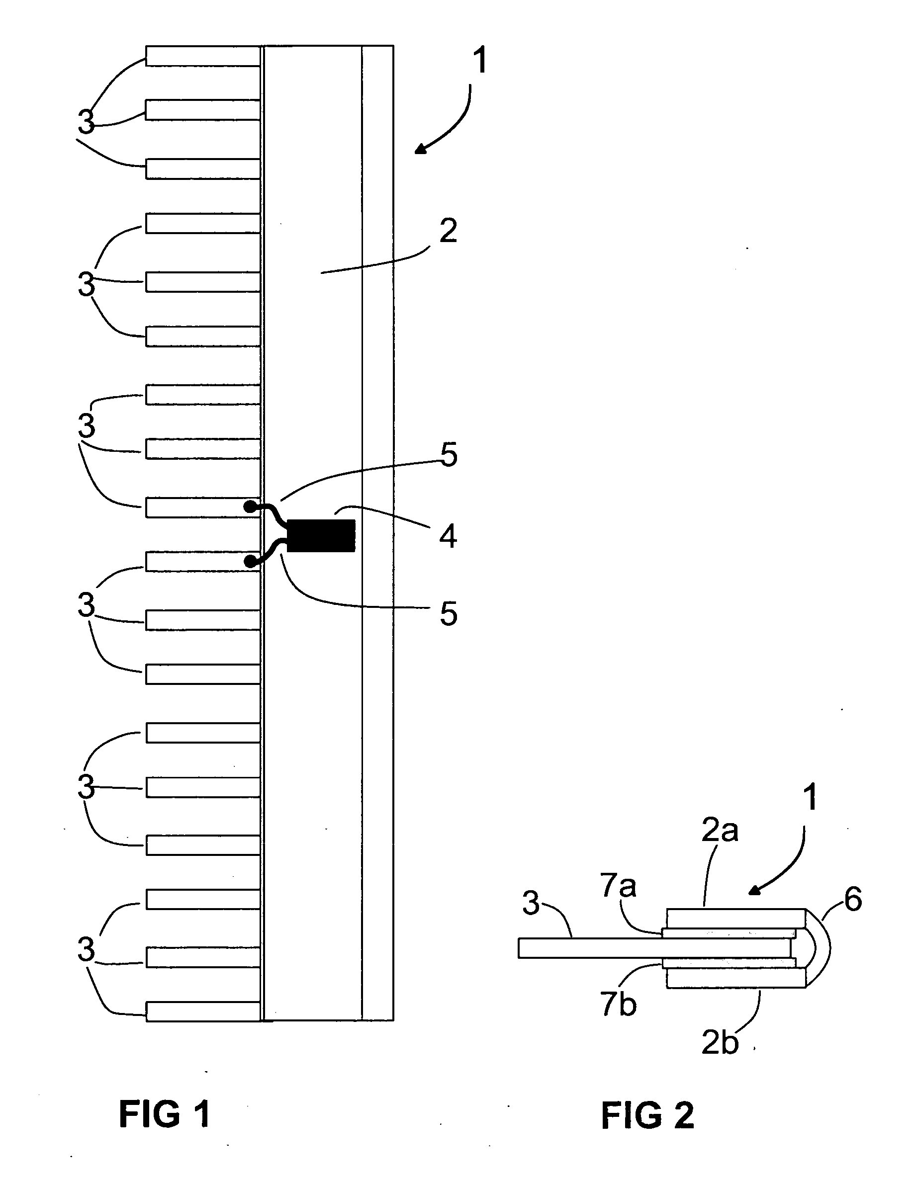
[0011]In FIG. 1 the number 1 indicates a temperature compensation element which includes a massive thermally-conductive strip 2, preferably a copper bar. Essentially at right angles to this strip are a series of electrically-conducting terminal lugs 3 pressed onto or glued onto the strip 2 in a row, with insulation material as thermally-conductive material being provided between the strip 2 and the terminal lugs 3 as well as between the individual terminal lugs 3. This means that the terminal lugs 3, which preferably also consist of copper, are electrically isolated from the strip 2 and from the other terminal lugs 3. The gap between the terminal lugs 3 arranged in a row is selected so that the terminal lugs 3 can be contacted in corresponding connection terminals of a front-panel connector of a process control module. This type of front-panel connector is for example known from DE 195 14 767 C1 or DE 19855245 195 14 768 C2. This front-panel connector can be plugged into a module an...


PUM


Abstract

The aim of the invention is to reduce the temperature gradient at the connection terminals of a connection unit to which lines can be joined. The inventive temperature compensation element is made of at least one first strip of thermally conducting material on which terminal lugs are arranged in a row at essentially right angles to the strip and are insulted in relation to each other and the strip. The terminal lugs are connected to the strip in a thermally conductive manner and can be respectively contacted to the lines with corresponding contact terminals of the connection unit.

Description

CROSS REFERENCE TO RELATED APPLICATIONS[0001]This application is the US National Stage of International Application No. PCT / DE2003 / 003288, filed Oct. 2, 2003 and claims the benefit thereof. The International Application claims the benefits of German application No. 10314406.4, filed Mar. 28, 2003, both applications are incorporated by reference herein in their entirety.FIELD OF INVENTION[0002]The invention relates to a temperature compensation element for a connection unit to which lines can be connected.SUMMARY OF THE INVENTION[0003]A connection unit in the form of a front-panel connector to which sensors or actors can be connected via lines is known from the Siemens catalog ST 70, page 4 / 114, 2003 edition. This front-panel connector can for example be plugged into a temperature measurement module to which thermal stress values from sensors can be fed via a number of input channels. To measure the temperature of a thermoelement as accurately as possible it is necessary to precisely...

Claims


Application Information

Patent Timeline
IPC IPC(8): H01R13/00G01K7/12H01R13/66
CPCH01R13/6683G01K7/12
Inventor KLUMPP, WOLFGANGMAIER, WILLISCHNEIDERHEINZE, WIGAND
Owner SIEMENS AG
Why Eureka
Eureka Blog
Learn More