Device for treatment of wounds with reduced pressure

a technology of wounds and devices, applied in the direction of suction pumps, other medical devices, dressings, etc., can solve the problems of disturbing the wound healing process, pain for patients, and inability to meet the needs of patients in all respects,

Active Publication Date: 2010-12-23
MOLNLYCKE HEALTH CARE AB
View PDF18 Cites 189 Cited by
  • Summary
  • Abstract
  • Description
  • Claims
  • Application Information

AI Technical Summary

Benefits of technology

[0039]According to one embodiment, the invention is characterized in that the interior of the tube has at least one diaphragm valve, which is arranged to only allow a flow in the direction away from the wound towards the underpressure source. Additional security against leakage back to the wound pocket is thereby achieved.

Problems solved by technology

Previously known devices for the vacuum treatment of wounds are not satisfactory in all respects.
A fundamental problem is that they are quite bulky right in front of the wound, which can result in the wound being able to be subjected by the bulky parts right in front of it to undesirable load stresses, which can be painful for the patient and can disturb the wound healing process.
A very major problem is the relatively rigid tubes which connect the wound pocket to the pressure source.
The tubes are unwieldy and bulky and can give rise to chafes and, in unfavourable cases, can also cause pressure sores on the patient.
Depending on where the patient has the wound, it is often not possible to place the pressure source or an intermediate fluid-receiving receptacle close to the wound, but instead it may be necessary to use relatively long tubes, for example from the foot of the patient right up to the waist, which can cause chafes on patients who are lying or sitting.
A further problem with conventional tubes is that it is difficult to achieve satisfactory leak-tightness at the connection between the tube and the sealing film placed over the wound.
If the underpressure for some reason abates, in previously known devices there is a risk of exudate which has previously been aspirated from the wound pocket being transported back and contaminating this, unless a check valve is present at the connection between the tube and the wound pocket.

Method used


Image

  • Device for treatment of wounds with reduced pressure
  • Device for treatment of wounds with reduced pressure
  • Device for treatment of wounds with reduced pressure

Examples


Embodiment Construction

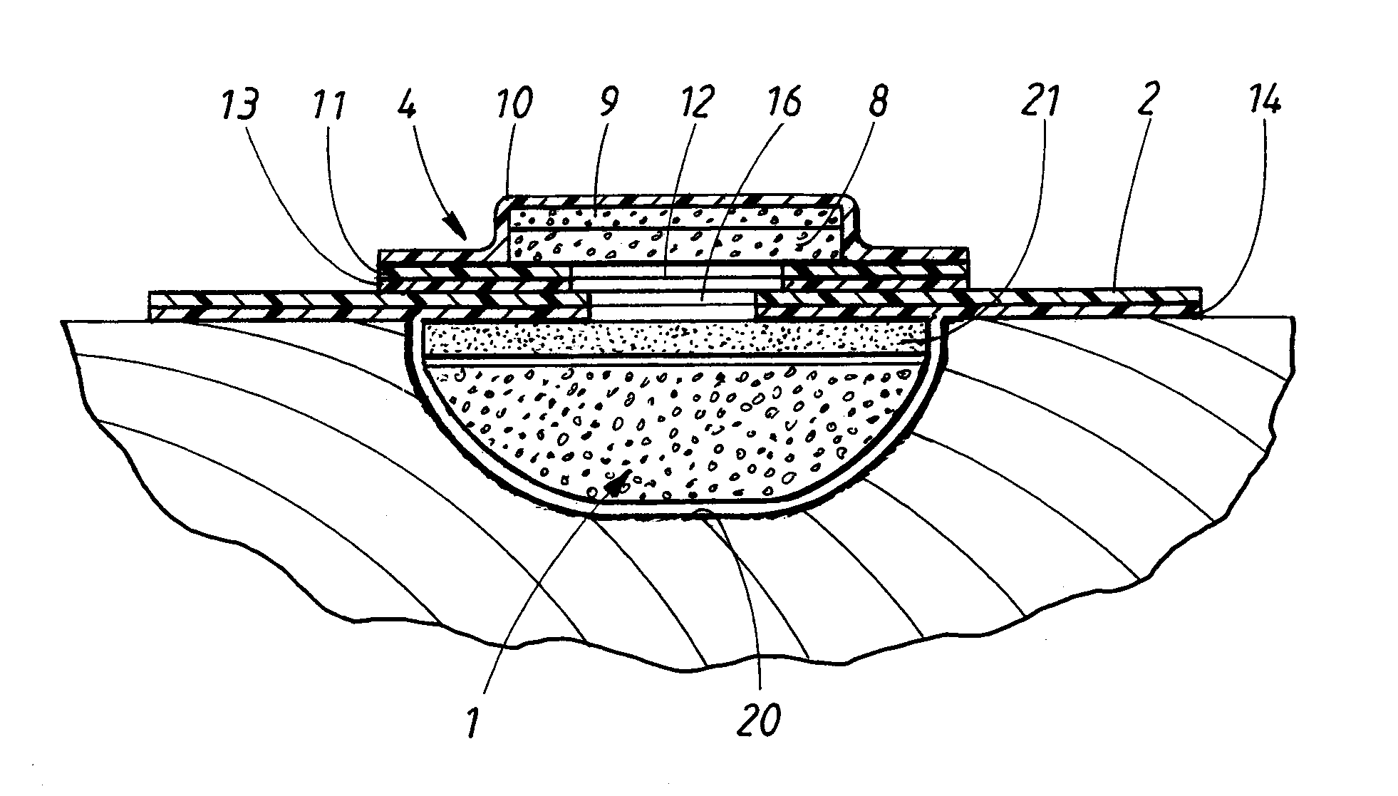
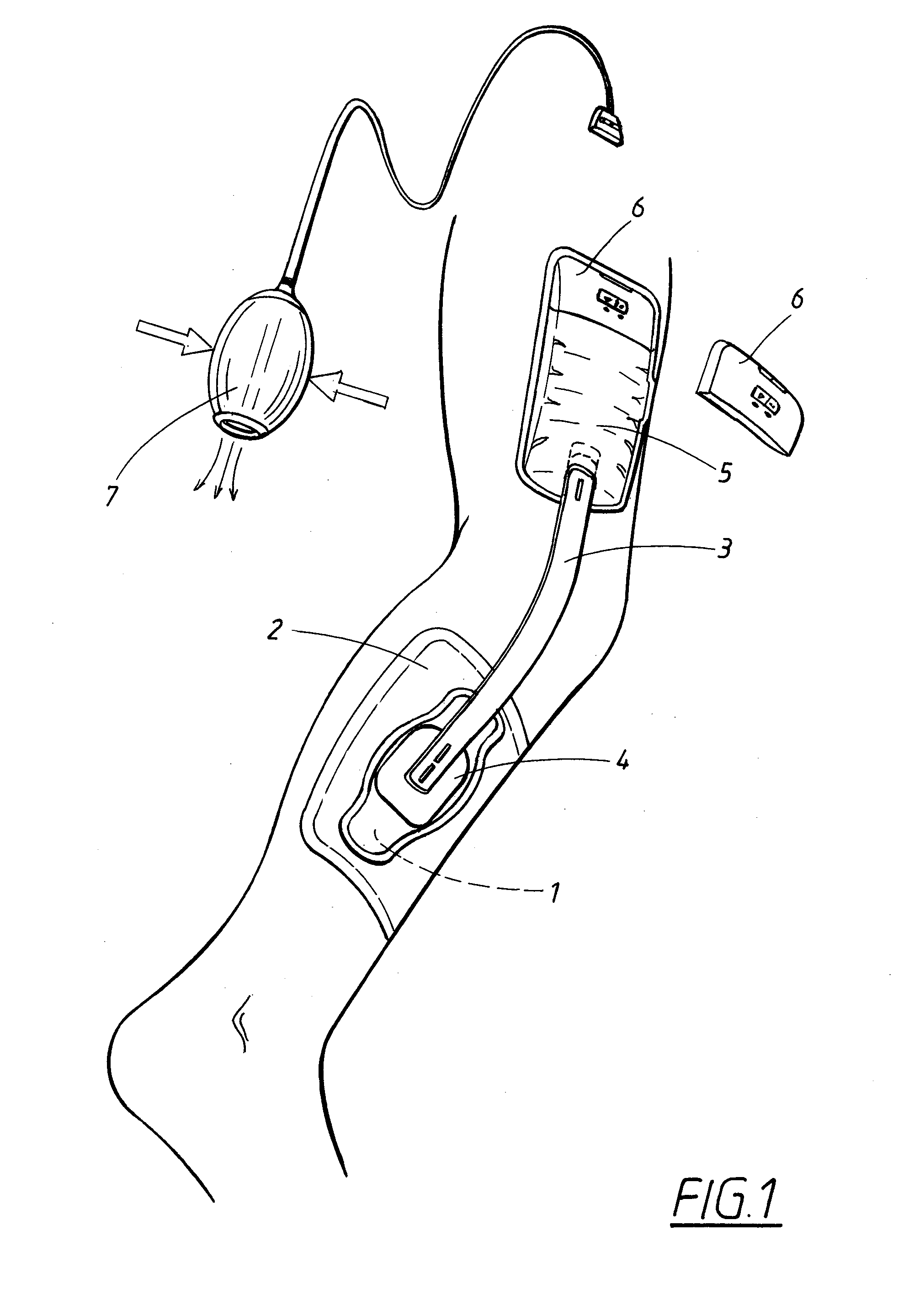
[0069]In FIG. 1, the patient has a wound on the calf. The device according to FIG. 1 comprises a hydrophobic, porous material piece 1, such as a hydrophobic, open-pored foam material. The material piece is cut to the shape of the wound to fill the wound pocket. A sealing film 2 is placed sealingly over the wound and is fixed to the skin of the user.

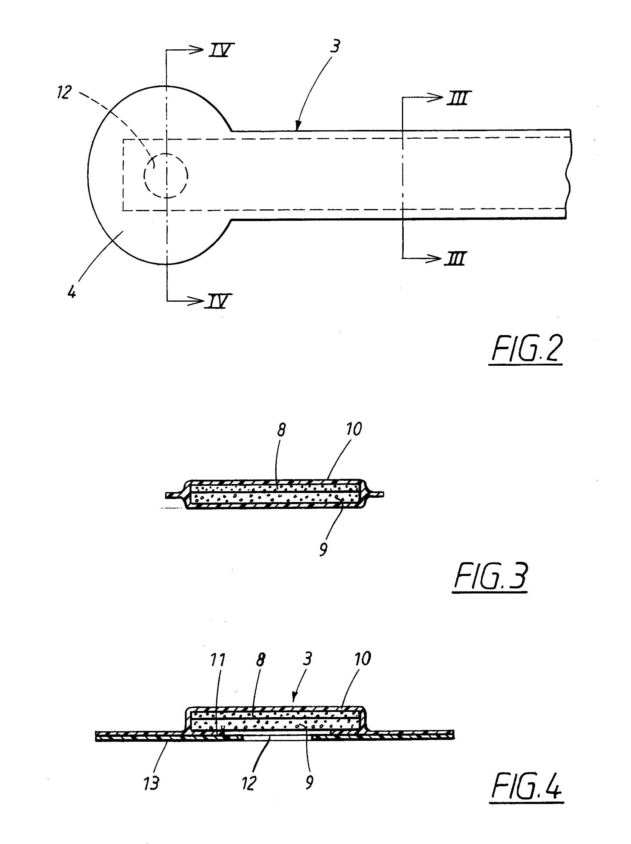
[0070]A tube 3 having a fixing member 4, which latter is fixed to the outer side of the sealing film over a hole made therein, connects the space in the wound pocket to an underpressure source 5. This is also intended to serve as a fluid-receiving element for fluid aspirated from the wound. The underpressure source is of elastically compressible configuration. Upon manual compression, air is squeezed out through a discharge valve (not shown), in the form of a one-way valve, to the environment. A further one-way valve (not shown) is fitted in the tube 3 or in the transition from the tube to the underpressure source. A suitable alternative ...


PUM


Abstract

Device for treating wounds with reduced pressure. The device comprises a sealing film, which is placed sealingly around the wound to cover the latter, an underpressure source, as well as a tube, which connects a space over the wound and beneath the sealing film to the underpressure source. The interior of the tube comprises a longitudinal first strand made of a hydrophobic material, as well as a second strand, made of an open-pored hydrophilic material, extending longitudinally over at least a part of the length of the tube. The said material strands are enclosed in a tube casing made of a flexible material.

Description

TECHNICAL FIELD[0001]The present invention relates to a device for treating wounds with reduced pressure, which device comprises a sealing film, which is intended to be placed sealingly around the wound and cover the latter, an underpressure source, as well as a tube, which is arranged to connect a space over the wound and beneath the sealing film to the underpressure source.BACKGROUND ART[0002]A number of methods for treating slow-healing wounds, such as infected wounds, diabetes sores, pressure sores or deep wounds, are previously known.[0003]Drainage of, for example, surgical wounds or other weeping wounds with underpressure is a standard treatment which has been used for decades. An example of a manual suction pump for this purpose is described in U.S. Pat. No. 3,742,952.[0004]U.S. Pat. No. 3,572,340 describes a pump in the form of an elastically compressible body made of an open-celled foam material, preferably a polyurethane foam, which body also serves as a receptacle for flu...

Claims


Application Information

Patent Timeline
Patent Type & Authority Applications(United States)
IPC IPC(8): A61M1/00
CPCA61F13/02A61M1/0066A61M1/0088A61M2205/8206A61M2027/004A61M2205/075A61M27/00A61F13/0206A61F13/0213A61F13/0226A61F13/0216A61M1/80A61M1/84A61M1/915A61M1/985A61M1/913A61M1/91
Inventor ANDRESEN, ANGELICAJOHANNISON, ULF
Owner MOLNLYCKE HEALTH CARE AB
Why Eureka
Try Eureka