Industrial Roll With Sensors Arranged To Self-Identify Angular Location

a technology of sensors and rolling pins, applied in the field of industrial rolls, can solve the problems of affecting the quality of paper produced with the paper machine, the cost of replacing an entire metallic roll,

Active Publication Date: 2010-12-23
STOWE WOODWARD
View PDF61 Cites 27 Cited by
  • Summary
  • Abstract
  • Description
  • Claims
  • Application Information

AI Technical Summary

Benefits of technology

[0010]The present invention can address some of the issues raised by prior industrial rolls. As a first aspect, embodiments of the present invention are directed to an industrial roll, comprising: a substantially cylindrical core having an outer surface; a polymeric cover circumferentially overlying the core outer surface; and a sensing system. The sensing system comprises: a plurality of sensors embedded in the cover, the sensors configured to detect an operating parameter of the roll and provide signals representative of the operating parameter, wherein one of the plurality of sensors is a tracking sensor and the remaining sensors are non-tracking sensors; and a processor operatively associated with the sensors that processes signals provided by the sensors. The sensors are arranged at a substantially equal radial distance from the core outer surface, such that they define a circle when viewed from an end of the roll. Each of the non-tracking sensors is further arranged at a substantially equal first angular distance from its immediate non-tracking sensor neighbors, two endmost non-tracking sensors defining an angular gap. The tracking sensor is disposed in the angular gap, such that a second angular distance defined by the tracking sensor and either of the endmost sensors differs from the first angular distance. In this configuration, the sensing system can identify from which sensor signals are generated without a trigger signal generator or accelerometer.

Problems solved by technology

Such rolls reside and operate in demanding environments in which they can be exposed to high dynamic loads and temperatures and aggressive or corrosive chemical agents.
Because papermaking rolls can have many different performance demands, and because replacing an entire metallic roll can be quite expensive, many papermaking rolls include a polymeric cover that surrounds the circumferential surface of a typically metallic core.
The magnitude of pressure applied with a roll can, therefore, impact the quality of paper produced with the paper machine.
However, this technique requires the equipment for producing and deciphering the trigger signal.

Method used


Image

  • Industrial Roll With Sensors Arranged To Self-Identify Angular Location
  • Industrial Roll With Sensors Arranged To Self-Identify Angular Location
  • Industrial Roll With Sensors Arranged To Self-Identify Angular Location

Examples


Embodiment Construction

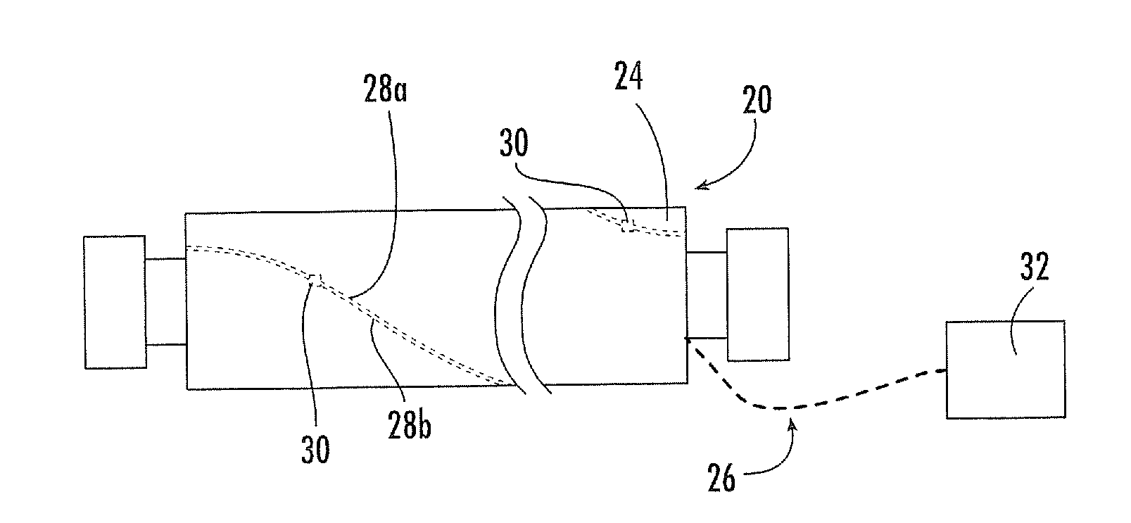
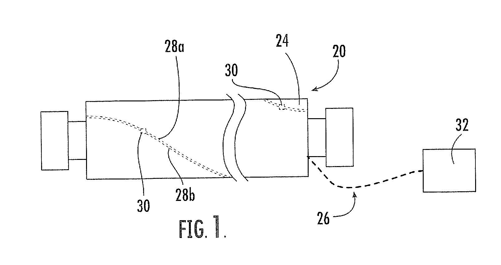
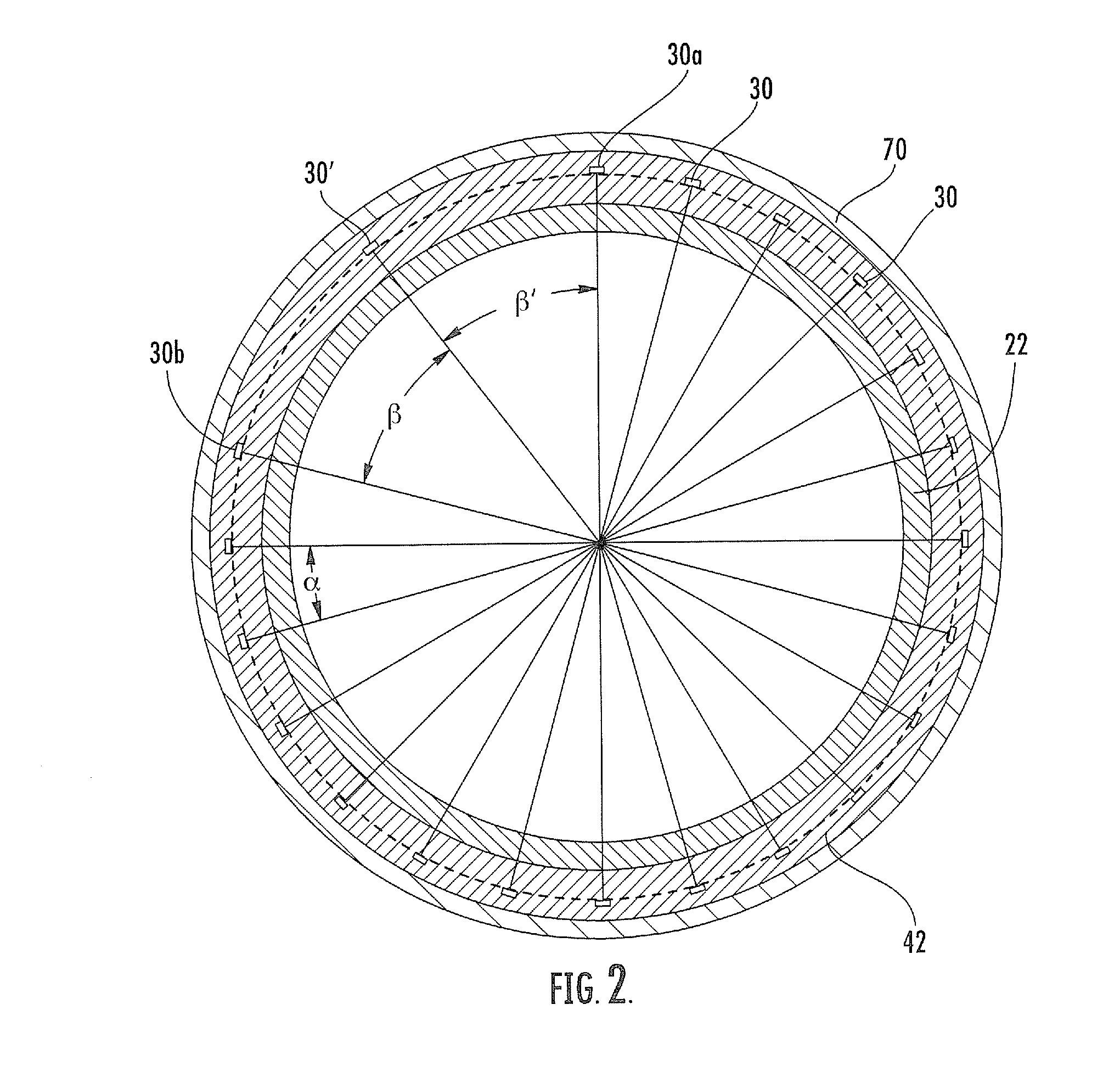
[0018]The present invention will be described more particularly hereinafter with reference to the accompanying drawings. The invention is not intended to be limited to the illustrated embodiments; rather, these embodiments are intended to fully and completely disclose the invention to those skilled in this art. In the drawings, like numbers refer to like elements throughout. Thicknesses and dimensions of some components may be exaggerated for clarity.

[0019]Well-known functions or constructions may not be described in detail for brevity and / or clarity.

[0020]Unless otherwise defined, all technical and scientific terms used herein have the same meaning as commonly understood by one of ordinary skill in the art to which this invention belongs. The terminology used in the description of the invention herein is for the purpose of describing particular embodiments only and is not intended to be limiting of the invention. As used in the description of the invention and the appended claims, ...


PUM


Abstract

An industrial roll includes: a substantially cylindrical core having an outer surface; a polymeric cover circumferentially overlying the core outer surface; and a sensing system. The sensing system comprises: a plurality of sensors embedded in the cover, the sensors configured to detect an operating parameter of the roll and provide signals representative of the operating parameter, wherein one of the plurality of sensors is a tracking sensor and the remaining sensors are non-tracking sensors; and a processor operatively associated with the sensors that processes signals provided by the sensors. The sensors are arranged at a substantially equal radial distance from the core outer surface, such that they define a circle when viewed from an end of the roll. Each of the non-tracking sensors is further arranged at a substantially equal first angular distance from its immediate non-tracking sensor neighbors, two endmost non-tracking sensors defining an angular gap. The tracking sensor is disposed in the angular gap, such that a second angular distance defined by the tracking sensor and either of the endmost sensors differs from the first angular distance. In this configuration, the sensing system can identify from which sensor signals are generated without a trigger signal generator or accelerometer.

Description

FIELD OF THE INVENTION[0001]The present invention relates generally to industrial rolls, and more particularly to rolls for papermaking.BACKGROUND OF THE INVENTION[0002]In a typical papermaking process, a water slurry, or suspension, of cellulosic fibers (known as the paper “stock”) is fed onto the top of the upper run of an endless belt of woven wire and / or synthetic material that travels between two or more rolls. The belt, often referred to as a “forming fabric,” provides a papermaking surface on the upper surface of its upper run which operates as a filter to separate the cellulosic fibers of the paper stock from the aqueous medium, thereby forming a wet paper web. The aqueous medium drains through mesh openings of the forming fabric, known as drainage holes, by gravity or vacuum located on the lower surface of the upper run (i.e., the “machine side”) of the fabric.[0003]After leaving the forming section, the paper web is transferred to a press section of the paper machine, wher...

Claims


Application Information

Patent Timeline
Patent Type & Authority Applications(United States)
IPC IPC(8): G01B7/14D21F7/06G01B7/00
CPCD21F3/06D21F3/08G01L5/102G01L5/0085G01L5/045D21G1/0233
Inventor PAK, KISANG
Owner STOWE WOODWARD
Why Eureka
Try Eureka