Continued Telecommunication with Weak Links

a technology of weak link and telecommunication, applied in the field of telecommunication, can solve the problems of information loss, delay is limited, and voice communication between end terminals via a network can be subject to the degradation of the communication link, and achieve the effect of improving speech processing

Inactive Publication Date: 2010-12-23
HIGHBRIDGE PRINCIPAL STRATEGIES LLC AS COLLATERAL AGENT
View PDF8 Cites 13 Cited by
  • Summary
  • Abstract
  • Description
  • Claims
  • Application Information

AI Technical Summary

Benefits of technology

[0032]The present invention has a number of advantages. With the present invention it is possible to continue communication between two end terminals even though the link between them is weak. This is according to one variation of the present invention solved through stopping real-time communication and instead buffering up speech packets. In this way users are allowed to speak in turns, while retaining the connection. This has the advantage of allowing the end users to decide if a communication session is to be ended when the link is weak as opposed to being forced by a network. Another advantage is that since speech packets are buffered, it is possible to provide improved processing of the speech so that there are no errors. This is often not possible in a real-time communication.

Problems solved by technology

Voice communication between end terminals via a network can be the subject of degradation of the communications link.
When the channel quality is low some information might be lost due to the weak radio channel.
The delay is however limited to a fractioseconds.
There are limits however.
Is the channel far to weak, then regular full-duplex voice communication even at the lowest coder rate cannot be supported and connections adropped by the network or are never admitted.
This is annoying especially for usersongoing calls whose link quality degrades over time and that are dropped by the netwithout prior notice.
No alternative communication service is offered by the network instead of the real-time voice service that is no longer available.
The known solutions addressing the above-mentioned problem are not satisfactory.

Method used


Image

  • Continued Telecommunication with Weak Links
  • Continued Telecommunication with Weak Links
  • Continued Telecommunication with Weak Links

Examples


Embodiment Construction

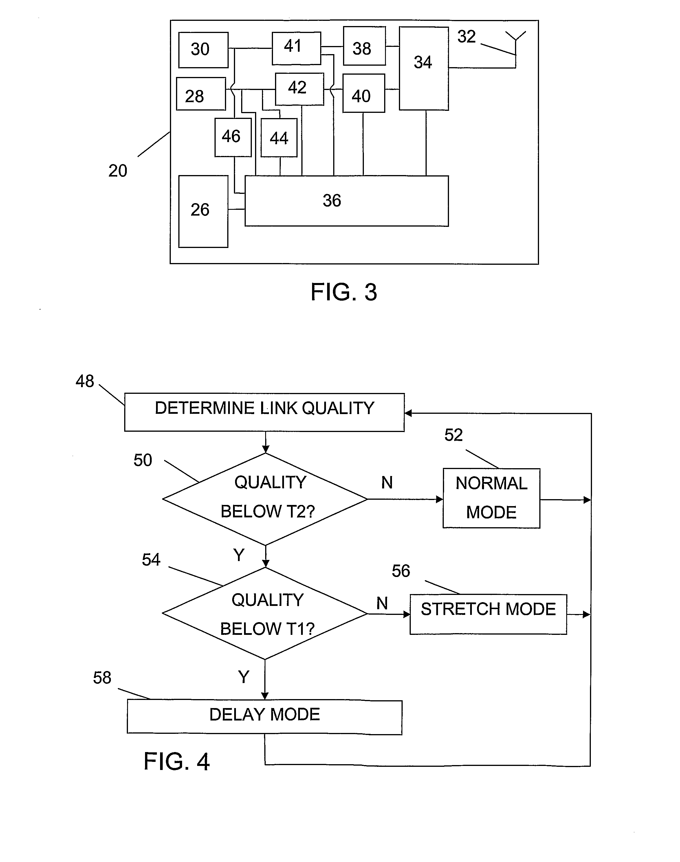
[0043]The present invention is directed towards allowing a voice communication session to continue between two communication terminals in case the link between them is weak.

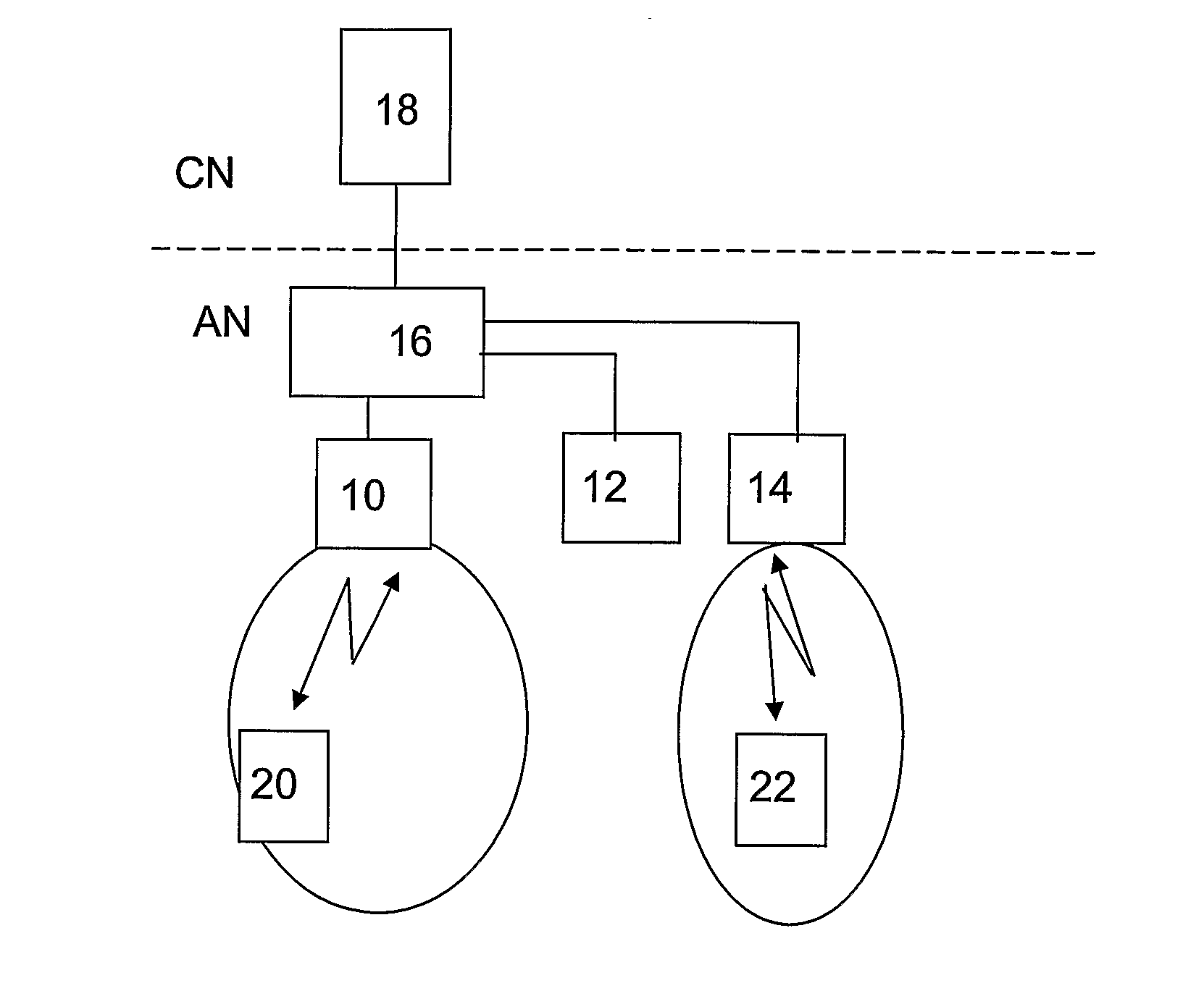
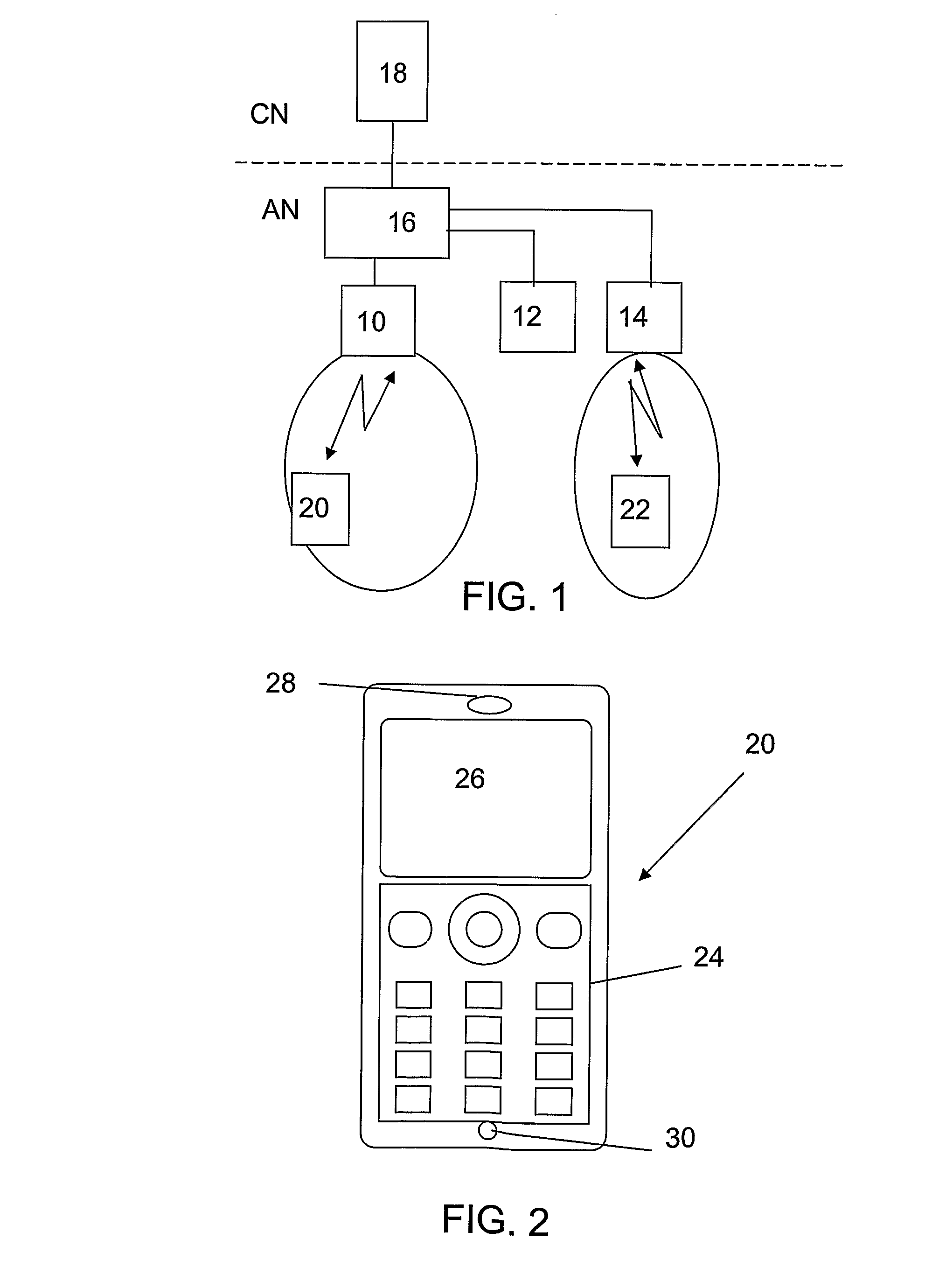
[0044]The present invention will now be described in more detail in the non-limiting example context of a wireless wide area network, which is here a Universal Mobile Telecommunications (UMTS) network that is shown in FIG. 1. However it should be realised that the invention may be applied in other types of wireless networks such as LTE (Long Term Evolution) networks or WLAN networks. The invention is in fact not limited to wireless networks, but can be applied in any type of communication network like a computer network. In the UMTS network of FIG. 1, there is a core network section CN that has a first service node 18, which may be a General Packet Radio Service (GPRS) node tailored to provide packet-switched type services, which is sometimes referred to as the serving GPRS service node (SGSN). The node 18 may be...


PUM


Abstract

According to the invention a receiving end terminal (RET) enters a delay mode based on the detecting of the quality of the link being lower than a threshold. In this delay mode, the receiving end terminal provides a reception delay indicator (RDI) for a sending end terminal (SET). The sending end terminal (SET) receives the reception delay indicator (RDI) and provides an end of speech indicator (ESI) for the receiving end terminal (RET) at an end of a speech coding interval (SC). The receiving end terminal (RET) uses the reception delay indicator (RDI) and end of speech indicator (ESI) to define a first time interval (AL1) during which a speech decoder is disabled. The speech decoder is again activated after the first time interval (AL1).

Description

TECHNICAL FIELD OF THE INVENTION[0001]The present invention relates to the field of telecommunication and especially telecommunication when communication links have low quality. More particularly the present invention relates to methods and devices for continuing communication betwea first and a second communication terminal normally engaged in duplex communicatiwhen the link between the two communication terminals is weak.DESCRIPTION OF RELATED ART[0002]Voice communication between end terminals via a network can be the subject of degradation of the communications link. This is especially the case for wireless netwoWith such voice communication, voice coders are normally used.[0003]Today there exist voice coders that support different voice qualities and data rates. In wireless communication network, the rate of the voice coder can be adapted based oe.g. the strength of the radio link or the load in the network. To support users communicating over weak radio links, a low rate (and h...

Claims


Application Information

Patent Timeline
Patent Type & Authority Applications(United States)
IPC IPC(8): G10L19/00H04B1/56H04W28/24H04W76/04H04W88/18
CPCH04W28/24G10L19/00H04W88/181H04W76/04H04W76/20
Inventor ALMGREN, MAGNUSBRUHN, STEFANSKILLERMARK, PER
Owner HIGHBRIDGE PRINCIPAL STRATEGIES LLC AS COLLATERAL AGENT
Why Eureka
Try Eureka