
Apparatus and methods for winding supports for coils and single poles of cores of dynamo electric machines

a technology supports, which is applied in the direction of metal working apparatus, inductance/transformer/magnet manufacture, manufacturing tools, etc., can solve the problems of early failure of dynamo electric machines, and achieve the effect of accurate deformation and increasing filling

Active Publication Date: 2010-12-30
ATOP SPA
View PDF5 Cites 17 Cited by
  • Summary
  • Abstract
  • Description
  • Claims
  • Application Information

AI Technical Summary

Benefits of technology

[0013]Accordingly, it is an object of the present invention to position the wire accurately in predetermined locations of the coil support during winding to form a coil.
[0014]It is a further object of the present invention to guarantee that the wire wound on the coil support is accurately deformed to be positioned along predetermined trajectories of the coil support, thereby increasing the filling.
[0015]It is also an object of the present invention to apply an accurate and predetermined deformation along the wire during winding to guarantee maximum filling and the integrity of the wire.

Problems solved by technology

The damage, if present, can be a source for early failure of the dynamo electric machine.

Method used


Image

  • Apparatus and methods for winding supports for coils and single poles of cores of dynamo electric machines
  • Apparatus and methods for winding supports for coils and single poles of cores of dynamo electric machines
  • Apparatus and methods for winding supports for coils and single poles of cores of dynamo electric machines

Examples


Embodiment Construction

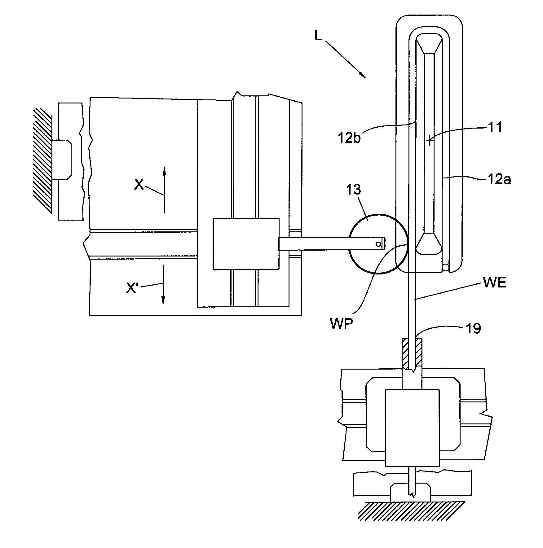
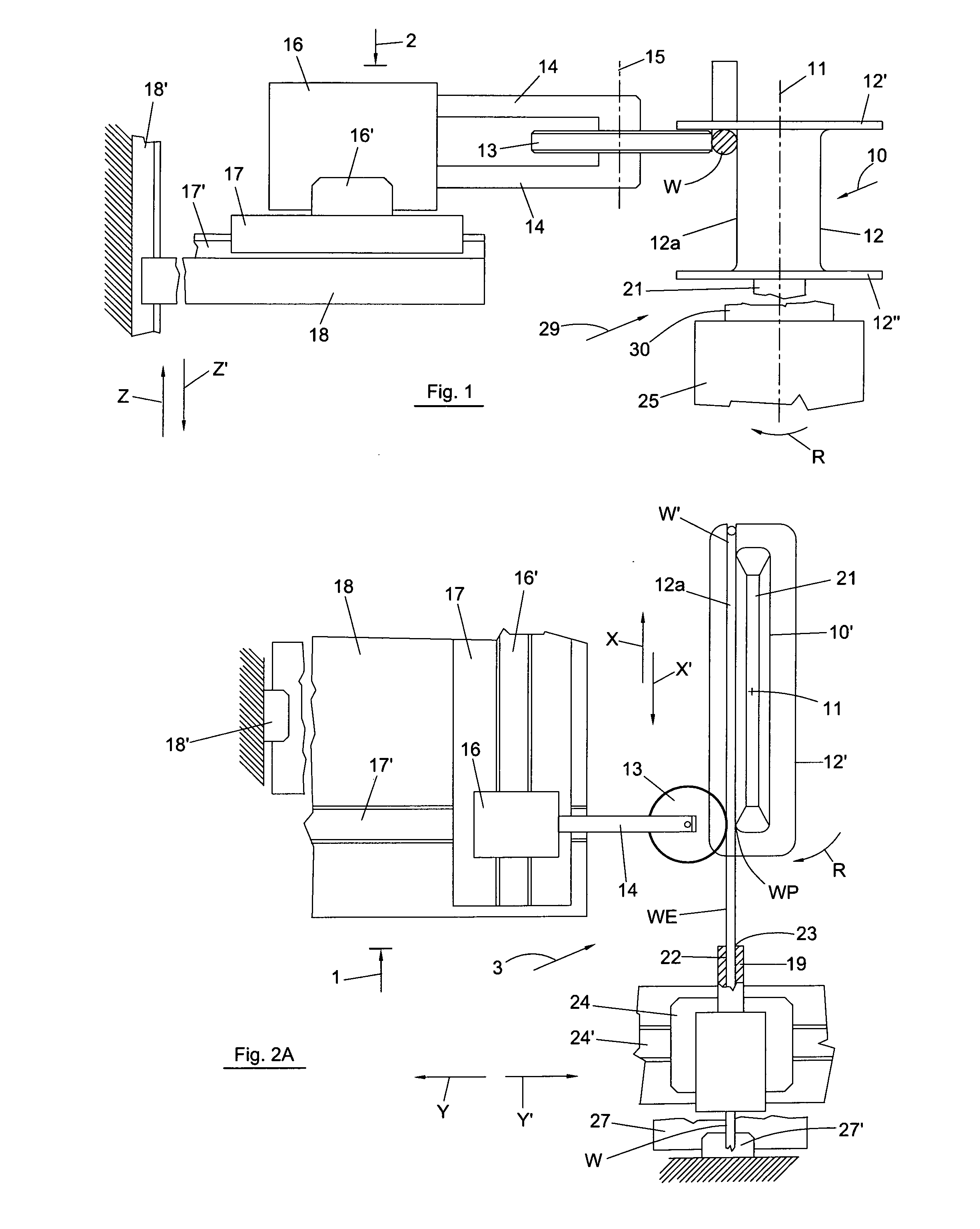
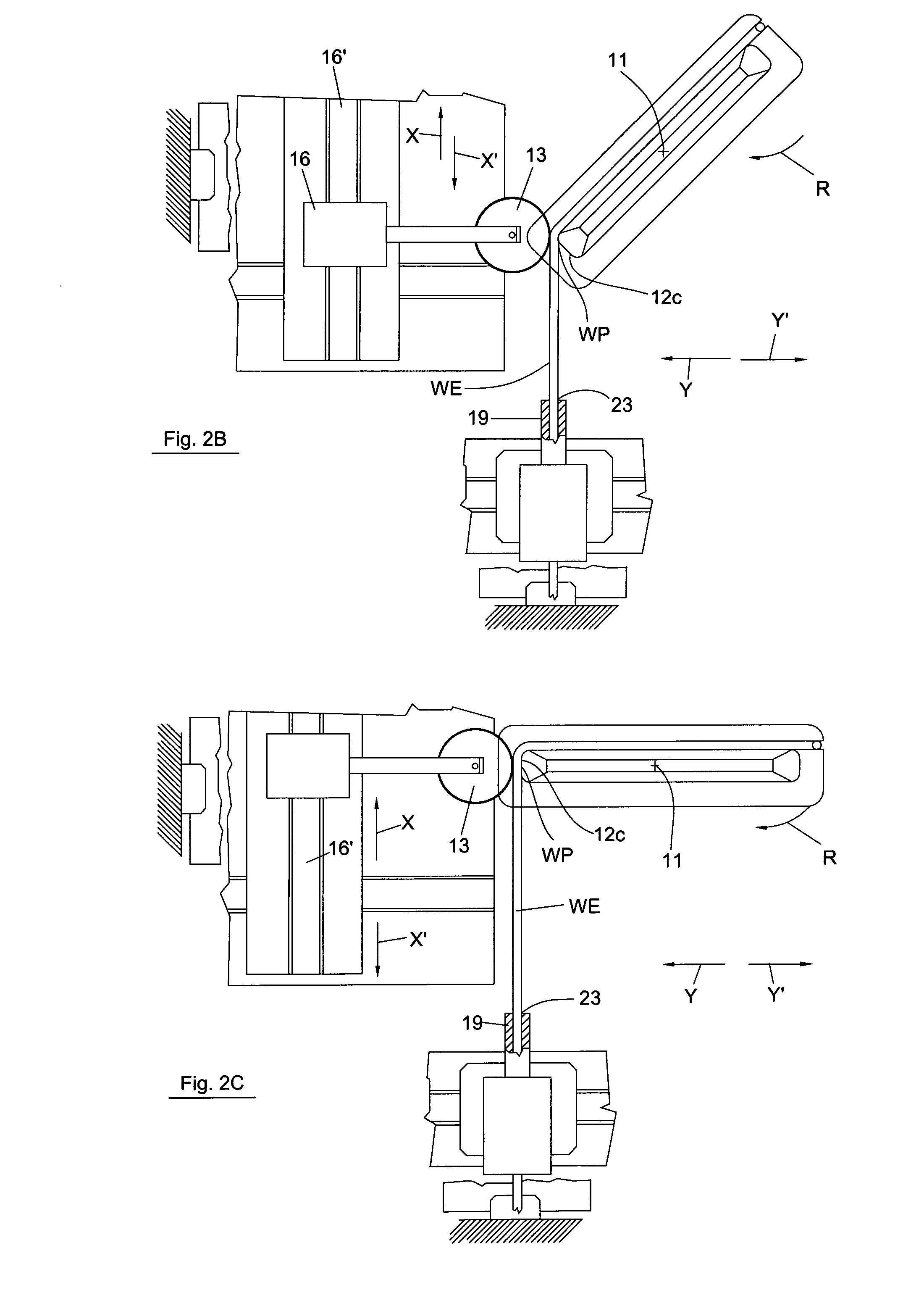
[0051]With reference to FIGS. 1 and 2 the apparatus of the invention is provided with an assembly 29 for holding and rotating a coil support 10. The assembly comprises a holding member 21, which becomes inserted in hollow portion 10′ of coil support 10.

[0052]Coil support 10 comprises a central portion 12 and opposite flanges 12′ and 12″. Wire W is wound around portion 12 up to flanges 12′ and 12″ to form a coil C of a certain number of turns, as shown in FIG. 3.

[0053]In FIGS. 2A-2E superior flange 12′ has been made transparent to show parts that would otherwise be hidden in the views from direction 2.

[0054]With reference to FIG. 2A, member 21 applies a grip on the internal surface of hollow portion 10′ to hold coil support 10 in alignment with rotation axis 11. Axis 11 can be aligned with an axis of symmetry of the coil support, as shown in FIGS. 1, 2A-2E. During winding, coil support 10 rotates with rotation R around axis 11 by rotating holding member 21 with drive unit 25.

[0055]As...


PUM

PropertyMeasurementUnit
distanceaaaaaaaaaa
pressureaaaaaaaaaa
speedaaaaaaaaaa

Abstract

Apparatus and method for winding at least one electric wire W on a coil support (10) of a core of a dynamo electric by using a wire dispensing member (19) means (21, 25) for rotating the coil support with respect to the dispensing member (19). It is foreseen to provide a relative movement of the dispensing member (19) with respect to the coil support (10) to maintain the angular orientation constant during winding. Furthermore it is foreseen to press on a portion (WP) of wire wound on the coil support (10) where the portion of wire (WP) is located immediately adjacent to a portion of wire that still has to be wound on the coil support (10). Engaging occurs also of the wire portion (WP) wound on the coils support and that extends to the dispensing member (19) when passage from one turn to another occurs for the stratification; the engagement occurring in opposition to the direction (Z′) of stratification of the wire. Pressing on the wire (W) can be accomplished in a direction (K) having an angle (E) that is more than zero and not perpendicular to an axis of the coil support.

Description

FIELD OF THE INVENTION[0001]The present invention relates to winding coils of dynamo electric machines.[0002]In particular the solutions of the invention concern winding coil supports or single poles where one or more electric conductors (in the following also referred to as wire) are wound to form a predetermined number of turns of a coil.DESCRIPTION OF THE PRIOR ART[0003]The supports for coils are made of insulation material and are assembled on the poles of cores after having being wound. Supports of this type have been described in JP 2003-244906.[0004]Single poles are portions of the core and are disassembled from the core when they are wound. After winding, the single poles are assembled one adjacent to the other to form the core; see EP 1098425.[0005]In the following the use of the terminology “coil support” contemplates both the supports for coils and single poles.[0006]The wire that needs to be wound can have a large cross section, therefore if it undergoes bending this wil...

Claims


Application Information

Patent Timeline
Patent Type & Authority Applications(United States)
IPC IPC(8): H02K15/00B23P19/00
CPCH02K15/095Y10T29/53161Y10T29/49009H01F41/064H01F41/082
Inventor PONZIO, MASSIMOSTRATICO, GIANFRANCOMUGELLI, MAURIZIO
Owner ATOP SPA
Learn More