System for joining a gondola to the concrete tower of an aerogenerator

a technology of aerogenerator and concrete, which is applied in the direction of motors, structural elements, building components, etc., can solve the problems of increasing manufacturing costs, difficult to achieve, and adding the problem of distributing tension as evenly as possible, so as to improve contact

Active Publication Date: 2010-12-30
NORDEX ENERGY SPAIN SA
View PDF29 Cites 42 Cited by
  • Summary
  • Abstract
  • Description
  • Claims
  • Application Information

AI Technical Summary

Benefits of technology

[0019]Finally, according to another preferred embodiment, in order to improve the contact between the flat annular support

Problems solved by technology

However, this has different drawbacks related to transport problems and an excessive increase in manufacturing costs.
However, there is a wide range of problems related to the joining of the last concrete section to the gondola of the aerogenerator and particularly to the bearing that allows the gondola to rotate around a vertical rotation axis, in order for the turbine of the aerogenerator to orient itself in accordance with the direction of the wind.
In these cases, the flatness requirement for yaw bearing seating would require a perfect ve

Method used


Image

  • System for joining a gondola to the concrete tower of an aerogenerator
  • System for joining a gondola to the concrete tower of an aerogenerator
  • System for joining a gondola to the concrete tower of an aerogenerator

Examples


Embodiment Construction

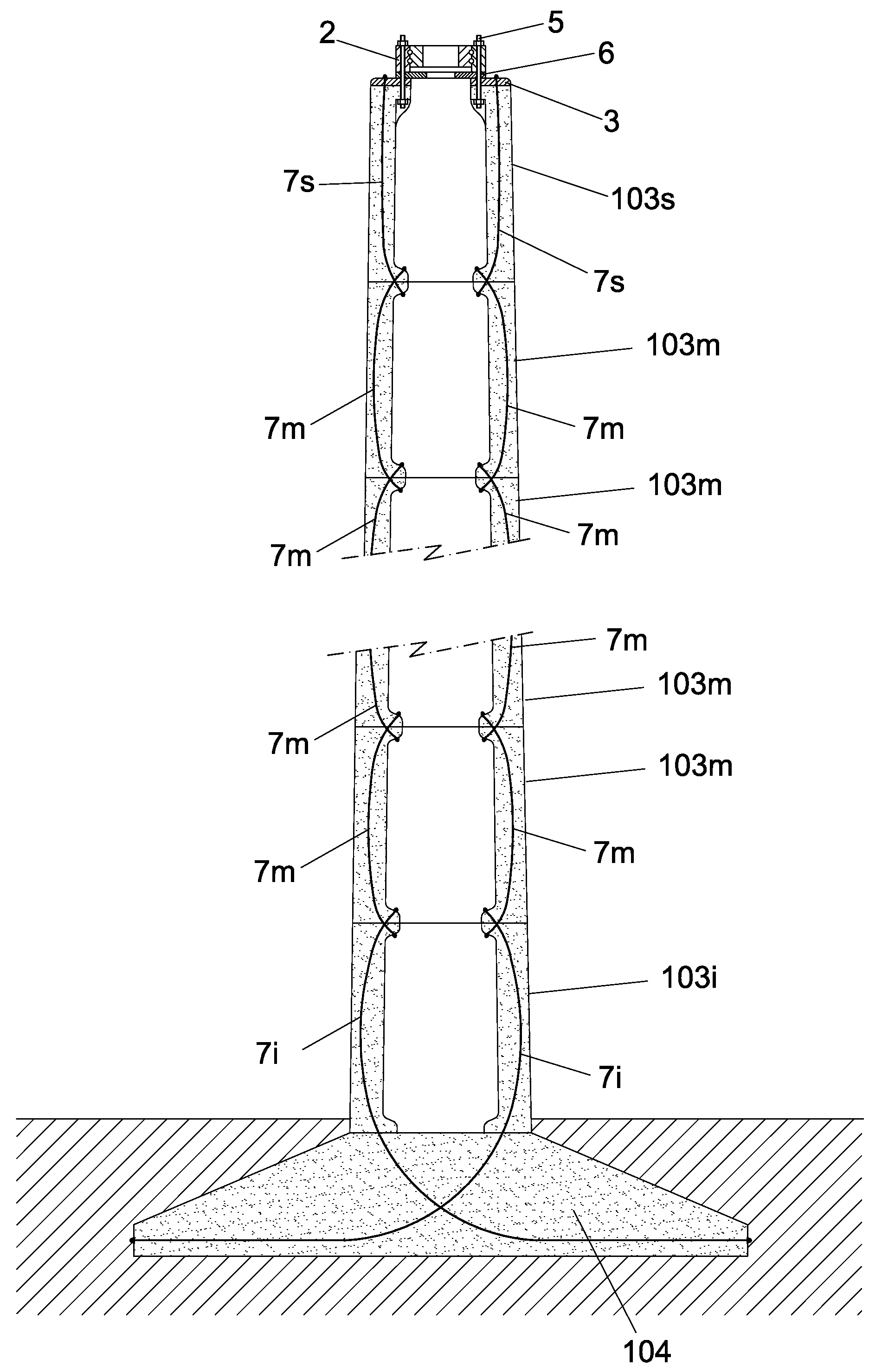
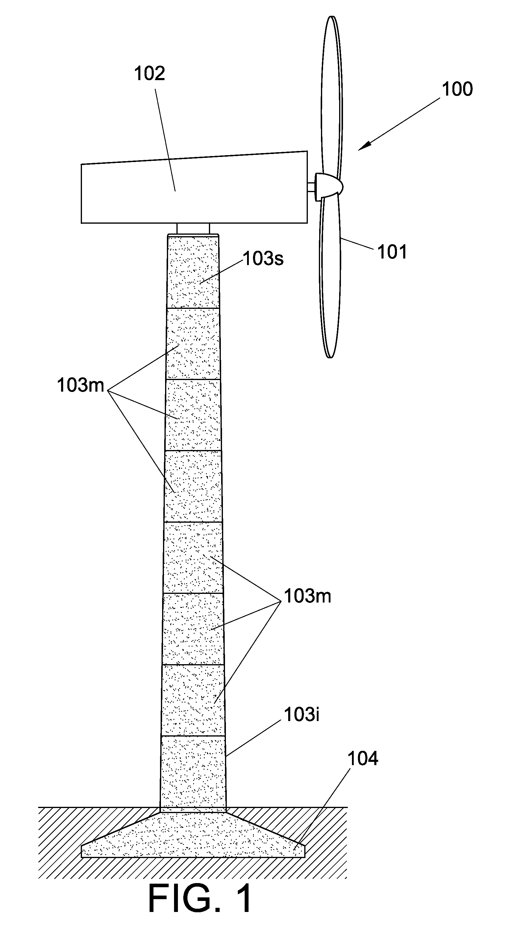
[0025]Some particular embodiments of the system (1) of the invention are described below, making reference to the attached figures. FIG. 1 represents the general diagram of an aerogenerator (100), wherein its constituent parts can be clearly observed: the aerogenerator (100) is formed by the rotor (101), the gondola (102) and the concrete tower (103). In turn, the concrete tower (103) is formed by an array of annular sections divided into an upper annular section (103s), intermediate annular sections (103m) and a lower annular section (103i), in addition to foundation (104).

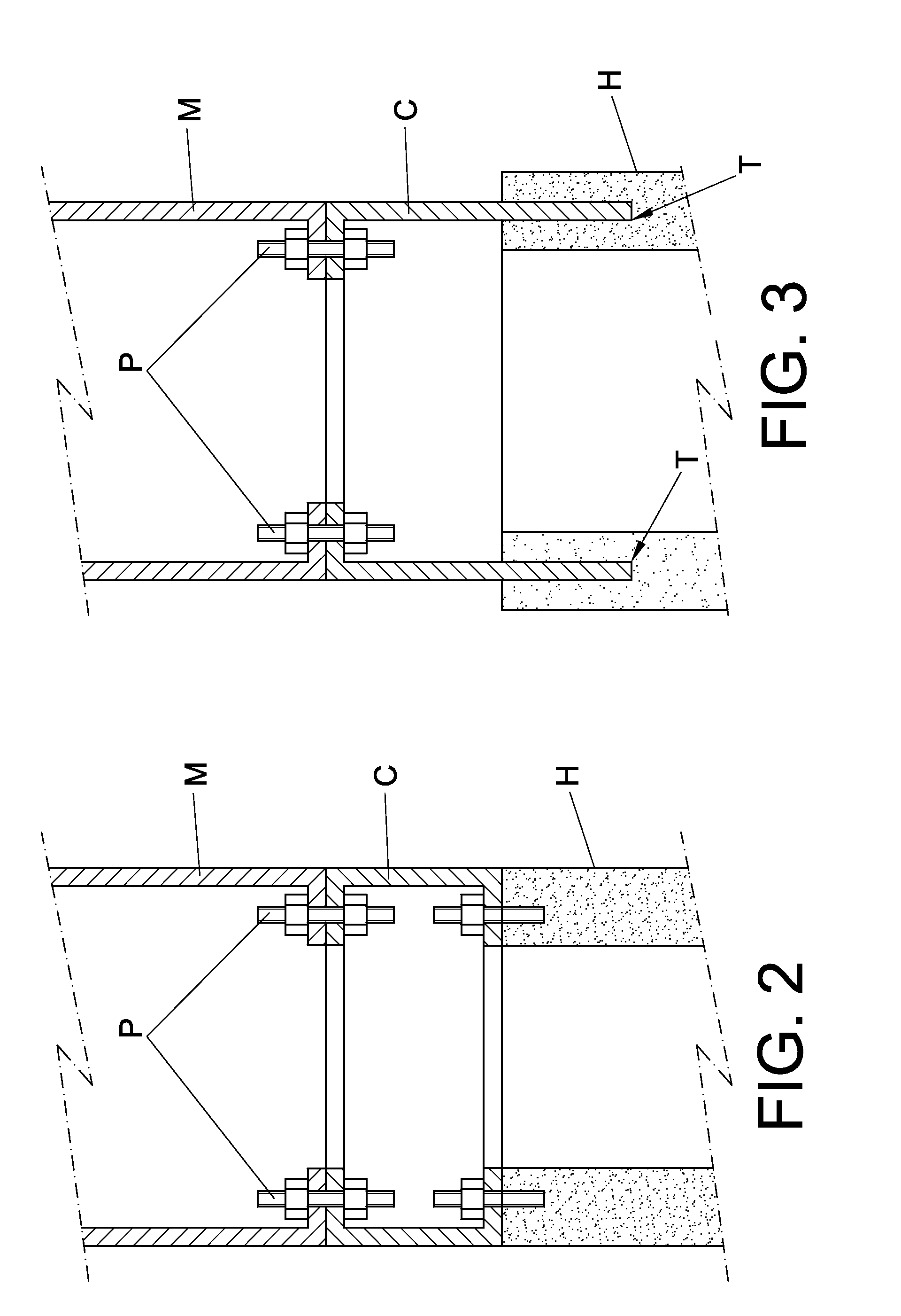
[0026]FIGS. 2 and 3 show examples of joining systems used in the prior art. Specifically, FIG. 2 shows a system that uses a mast (C) to establish the joint between a metallic section (M) and a concrete section (H) of a tower, where bolts are used to join parts by means of upper and lower clamps of the mast (C). FIG. 3, on the other hand, shows a system where the lower portion of the mast (C) lacks a clamp and is ...


PUM


Abstract

The present disclosure describes a system for joining a gondola to the concrete tower of an aerogenerator, wherein the concrete tower is formed by a lower annular section, one or several intermediate annular sections and an upper annular section, including a flat annular support which is inserted between an upper surface of the upper annular section of the tower and the lower surface of a yaw bearing that supports the gondola, the flat annular support comprising orifices wherethrough a plurality of joining means pass, each of which is fixed to the bottom of the upper annular section of the tower and to the bottom of the yaw bearing.

Description

OBJECT OF THE INVENTION[0001]The object of the present invention is a simple, quick and cheap system for joining the gondola of an aerogenerator to the last section of a concrete tower. To this end, a flat annular support is fixed to the yaw bearing that supports the gondola and to the upper concrete section of the tower by means of pass-through bolts and / or tension cables.BACKGROUND OF THE INVENTION[0002]The evolution of wind power generation technology is currently aimed at designing aerogenerators with increasingly larger power outputs, which implies an increase in the size of the constituent parts of the aerogenerators. The development of higher towers must be carried out taking into account a set of design criteria, such as load, resistance of the material and dynamic performance, in addition to construction, transport and installation conditions.[0003]Towers up to 80 m in height are usually manufactured from tubular metal sections. However, it has been verified that more resis...

Claims


Application Information

Patent Timeline
IPC IPC(8): E04B1/21E04H12/00
CPCE04H12/085F03D1/00F03D11/04F05B2240/40E04H12/12E04H12/16Y02E10/728F03D13/20Y02E10/72E04B1/215E04H12/08F03D7/0212
Inventor GARC A MAESTRE, IVANAZANZA LADRON, EDUARDOGARC A SAYES, JOSE MIGUELNUNEZ POLO, MIGUEL
Owner NORDEX ENERGY SPAIN SA
Why Eureka
Try Eureka