Direction control valve for shower irrigating applications

a direction control valve and irrigating technology, applied in mechanical equipment, functional valve types, transportation and packaging, etc., can solve the problems of surrounding property, affecting the safety of users, so as to reduce the pressure of the valve

Inactive Publication Date: 2010-12-30
NANMA MFG
View PDF11 Cites 111 Cited by
  • Summary
  • Abstract
  • Description
  • Claims
  • Application Information

AI Technical Summary

Benefits of technology

[0010]Embodiments of the presently described technology also provide a method for releasing pressure in a direction control valve. The method includes providing a path of fluid flow through the valve from an inlet port to a first outlet port via first and second orifices and reducing pressure in the valve through a second outlet port by at least one of rupturing a thin-walled portion of the valve and moving a portion of a wall in the valve.

Problems solved by technology

When the device fails, the device can explode and injure persons and damage property in the vicinity of the device.
The types of direction control valves currently available have a number of limitations.
For example, many existing valves do not have sufficient safeguards to protect users and surrounding property from explosions that can result due to a build-up of pressure in the valve.
In addition, currently available valves are not easily installed, removed and operated by users.
These valves also typically have very ineffective sealing capabilities.
That is, currently available flow-direction valves generally leak water during their operation.
Currently available valves also tend to be manufactured at a substantial cost.

Method used


Image

  • Direction control valve for shower irrigating applications
  • Direction control valve for shower irrigating applications
  • Direction control valve for shower irrigating applications

Examples


Embodiment Construction

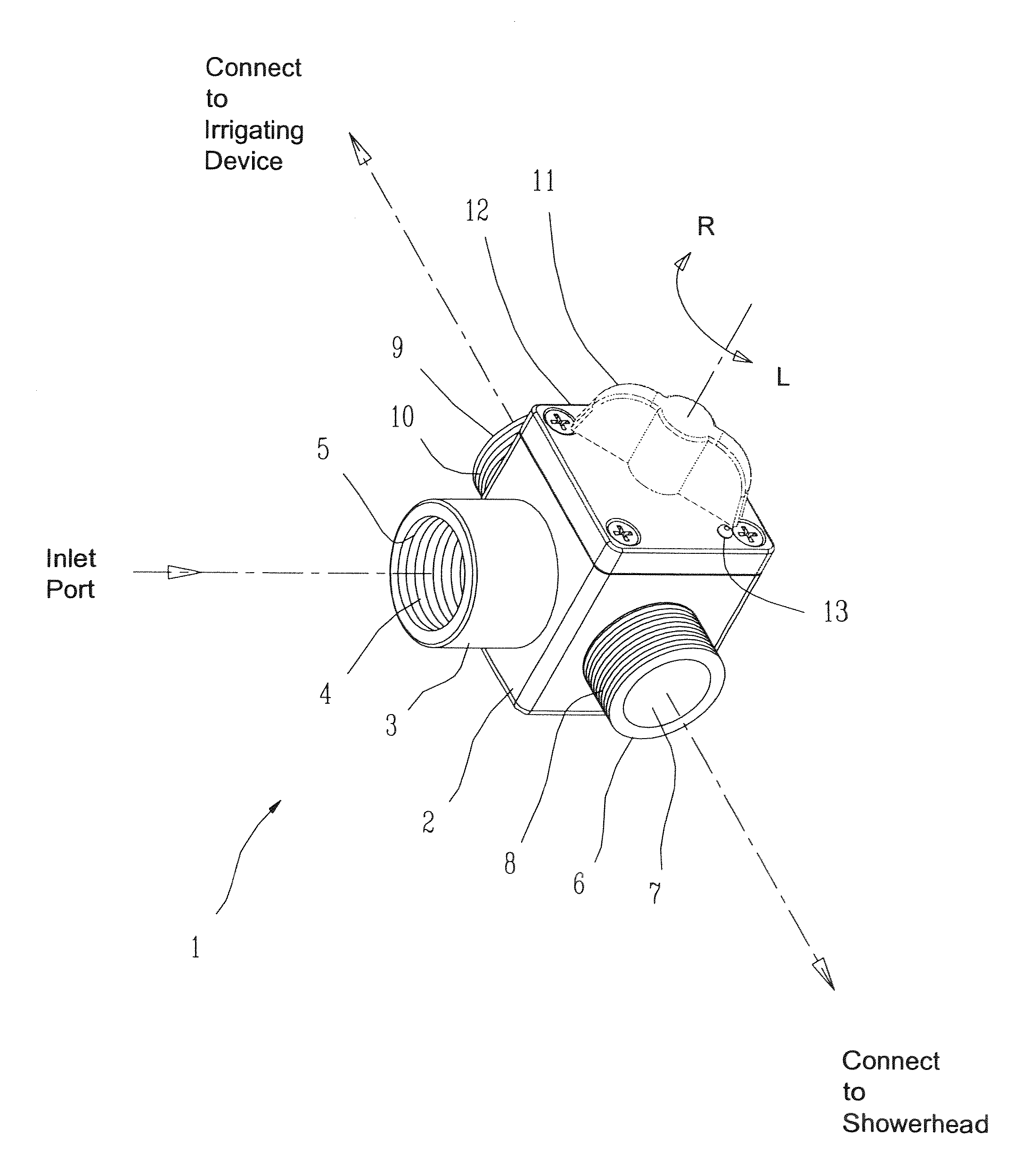
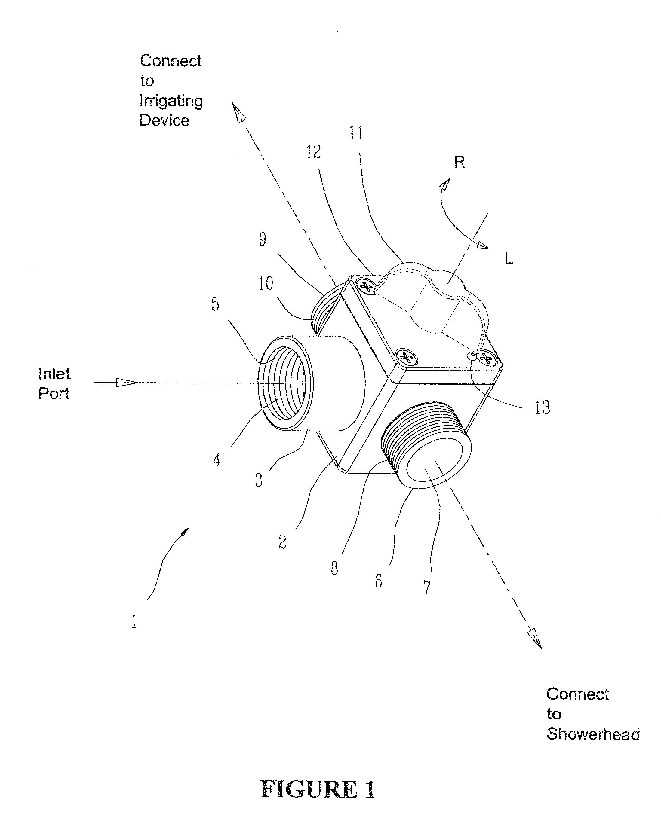
[0022]In accordance with embodiments of the presently described technology, a hydraulic direction control valve is provided for directing the flow of fluid from an inlet port to various outlet ports. The valve can comprise a main body with an inlet port and two outlet ports, a rotational spool, a turning knob attached to the rotational spool, and a cover to retain the rotational spool inside the main body.

[0023]Embodiments of the presently described valve can include a pressure relief apparatus included in the rotational spool. The pressure relief apparatus can include a destructive or non-destructive mechanism. That is, the pressure relief apparatus can be destroyed (and no longer operable) once fluid pressure in the valve is relieved (the destructive mechanism) or not destroyed and capable of being used again once fluid pressure in the valve is relieved (the non-destructive mechanism).

[0024]Embodiments of the presently described valve can also include an improved seal. For example...


PUM


Abstract

Embodiments of the presently described technology provide a direction control valve including first and second orifices and a pressure release mechanism. The first and second orifices provide a path of fluid flow through the valve from an inlet port to a first outlet port. The pressure release mechanism is configured to reduce pressure in the valve through a second outlet port. Embodiments of the presently described technology also provide a direction control valve including first and second fluid communication paths. The first fluid communication path is defined by an inlet port, first and second orifices, and a first outlet port. The second fluid communication path is defined by the inlet port, the first orifice, a pressure release mechanism, and a second outlet port. The second fluid communication path of the valve does not exist until an internal pressure of the valve exceeds a predetermined threshold.

Description

CROSS-REFERENCE TO RELATED APPLICATIONS[0001]This application is a divisional application and claims the benefit of U.S. patent application entitled “Direction Control Valve for Shower Irrigating Applications”, Ser. No. 11 / 710,793, filed Feb. 26, 2007, the entire contents of which are herein incorporated by reference.BACKGROUND OF THE INVENTION[0002]The presently described invention generally relates to hydraulic valves. More specifically, embodiments of the presently described technology provide an improved valve for safely controlling the pressure in and direction of fluid flow through the valve.[0003]In applications where fluid is diverted or directed from a source, pressure can build in the device or apparatus used to direct the fluid. At a certain point, the pressure internal to the device or apparatus can reach a level at which the device fails. When the device fails, the device can explode and injure persons and damage property in the vicinity of the device.[0004]For example,...

Claims


Application Information

Patent Timeline
Patent Type & Authority Applications(United States)
IPC IPC(8): F16K17/14
CPCF16K11/0853Y10T137/1632Y10T137/2652Y10T137/0396
Inventor NAN, SIMON SIU MAN
Owner NANMA MFG
Why Eureka
Try Eureka