Above ground water clarifier

Active Publication Date: 2010-12-30
ENNIS G THOMAS
View PDF22 Cites 4 Cited by
  • Summary
  • Abstract
  • Description
  • Claims
  • Application Information

AI Technical Summary

Benefits of technology

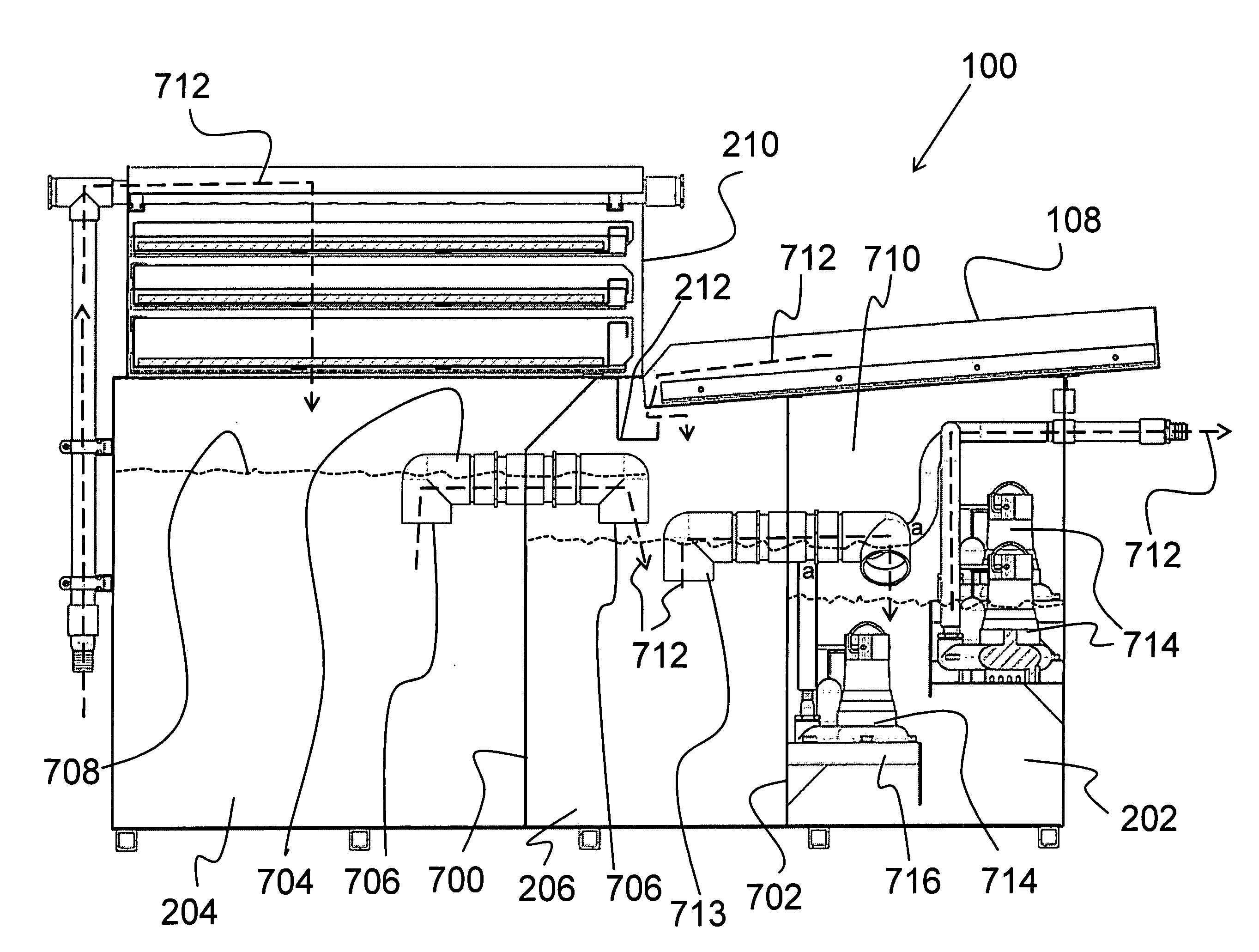
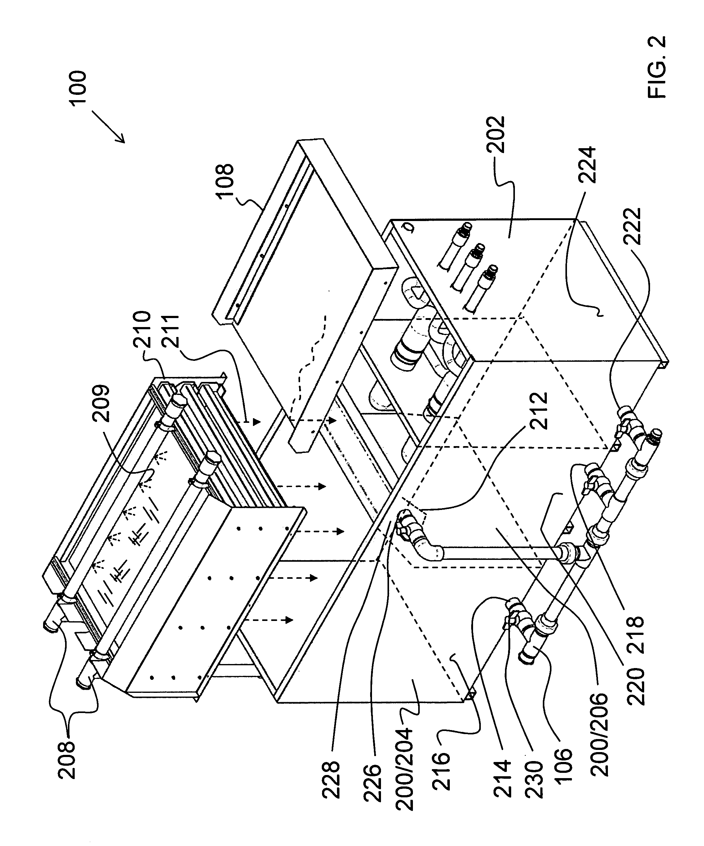
[0015]In yet another aspect, the recovery chamber further comprises a first recovery chamber disposed directly beneath the filter tray rack for separating solids and/or oil from the water and a second recovery chamber separated from the first recovery chamber by a baffle and disposed adjacent to the first recovery chamber. The first recovery chamber is fluidly connected

Problems solved by technology

Recovered water is usually quite dirty, and particulates and oily residues must be removed from the contaminated water before recycling through the system.
This arrangement, and other commercially available filter systems, are not ideal, however, in that they all use a below-ground water clarifier.
Because of the below-ground positioning, the tanks are difficult t

Method used


Image

  • Above ground water clarifier
  • Above ground water clarifier
  • Above ground water clarifier

Examples


Example

[0031]The following description is presented to enable one of ordinary skill in the art to make and use the invention and to incorporate it in the context of particular applications. Various modifications, as well as a variety of uses in different applications will be readily apparent to those skilled in the art, and the general principles defined herein may be applied to a wide range of embodiments. Thus, the present invention is not intended to be limited to the embodiments presented, but is to be accorded the widest scope consistent with the principles and novel features disclosed herein.

[0032]In the following detailed description, numerous specific details are set forth in order to provide a more thorough understanding of the present invention. However, it will be apparent to one skilled in the art that the present invention may be practiced without necessarily being limited to these specific details. In other instances, well-known structures and devices are shown in block diagr...


PUM

PropertyMeasurementUnit
Angleaaaaaaaaaa
Sizeaaaaaaaaaa
Gravityaaaaaaaaaa

Abstract

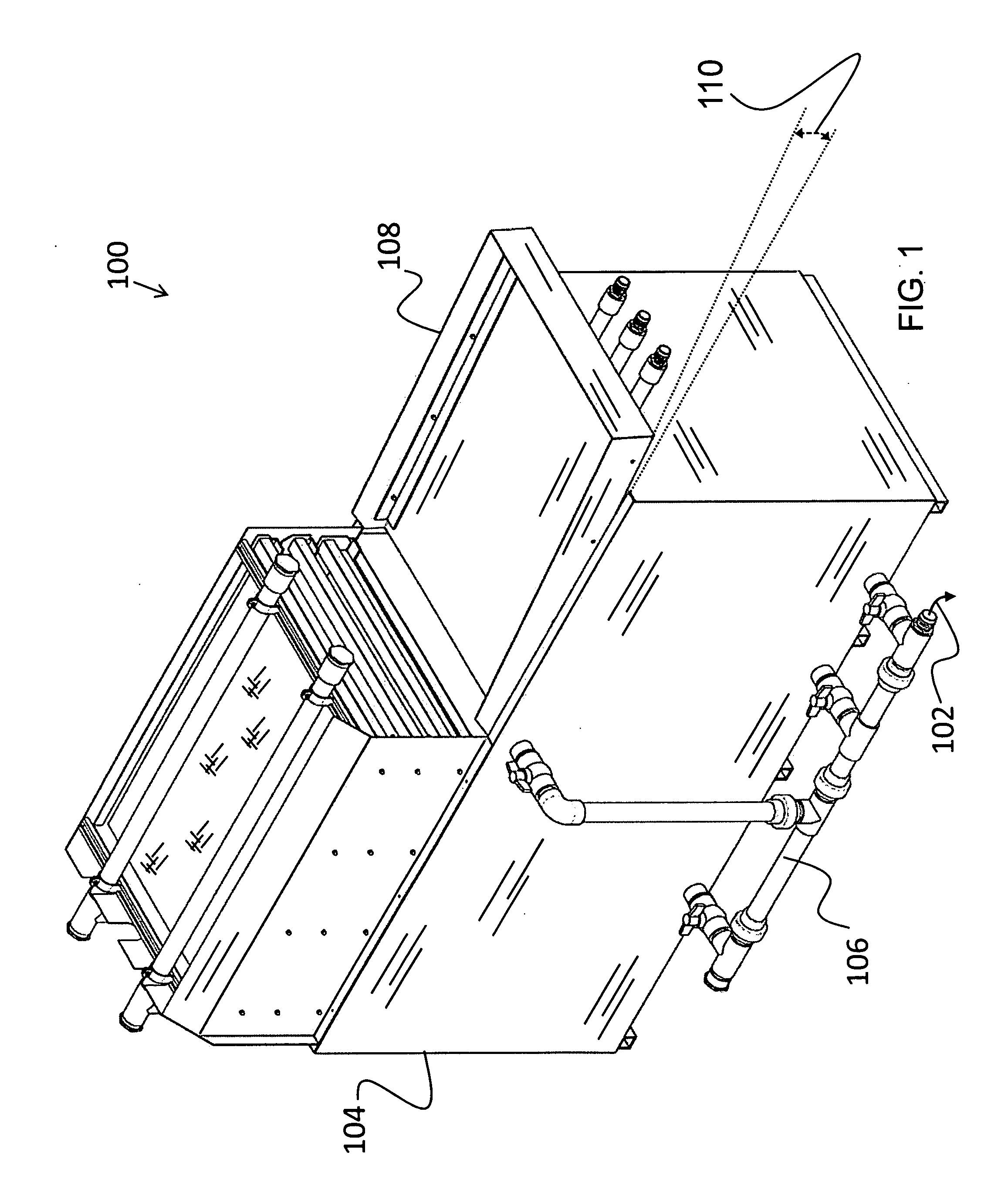
An above ground water clarifier is described. The clarifier includes a spray system for receiving water from an external system and disposing the water onto a filter tray rack. A first recovery chamber is positioned below the filter tray rack for receiving filtered water that is gravity fed through the filter tray rack. A second recovery chamber is positioned adjacent to and fluidly connected with the first recovery chamber. The first and second recovery chambers are formed to filter out solids and/or oils before passing the water to a sump chamber and/or the sewer. The sump chamber includes a plurality of tiered pumps for pumping the water back to the external system.

Description

PRIORITY CLAIM[0001]The present application is a Non-Provisional Utility patent application of U.S. Provisional Application No. 61 / 269,837, filed on Jun. 30, 2009, entitled, “Above Ground Reclaim System.”BACKGROUND OF THE INVENTION[0002](1) Field of Invention[0003]The present invention relates to a water clarification system and, more particularly, to an above ground water clarifier for use with an external system for cleaning, storing, and recycling water from the external system.[0004](2) Description of Related Art[0005]Water clarification and reclamation systems have long been known in the art. Such systems have been used in a variety of operations for capturing, cleaning and recycling the water used in the operations. By way of example, automatic vehicle-washing systems are well-known, and are in widespread use for washing passenger automobiles, trucks, buses, railroad equipment, and the like. A typical system includes a conveyor for moving the vehicle through the installation, ...

Claims


Application Information

Patent Timeline
IPC IPC(8): B01D36/00
CPCB01D29/05B01D29/58
Inventor ENNIS, G. THOMAS
Owner ENNIS G THOMAS
Why Eureka
Try Eureka