Welding control system

a control system and welding technology, applied in non-electric welding apparatus, laser beam welding apparatus, manufacturing tools, etc., can solve problems such as unsatisfactory weld beads, welder relative to workpieces may not be properly configured, and defects may develop during automated welding operations

Inactive Publication Date: 2010-12-30
GENERAL ELECTRIC CO
View PDF16 Cites 88 Cited by
  • Summary
  • Abstract
  • Description
  • Claims
  • Application Information

AI Technical Summary

Problems solved by technology

Defects may develop during automated welding operations due to improper welder settings.
For example, an output power of a welder, a feed rate of material into the welding zone and / or a speed of the welder relative to a workpiece may not be properly configured for a particular welding operation.
These improper settings may result in unsatisfactory weld beads.
For example, the weld bead may not have a proper height, width and / or penetration depth into the workpiece.
Furthermore, the welder may wear away workpiece material surrounding the welding zone, a condition known as undercut.
Such defects may degrade weld quality, thereby resulting in a weaker joint.
Moreover, additional time-consuming and expensive finishing operations may be performed to correct the defects.

Method used


Image

  • Welding control system
  • Welding control system
  • Welding control system

Examples


Embodiment Construction

[0015]One or more specific embodiments of the present invention will be described below. In an effort to provide a concise description of these embodiments, all features of an actual implementation may not be described in the specification. It should be appreciated that in the development of any such actual implementation, as in any engineering or design project, numerous implementation-specific decisions must be made to achieve the developers' specific goals, such as compliance with system-related and business-related constraints, which may vary from one implementation to another. Moreover, it should be appreciated that such a development effort might be complex and time consuming, but would nevertheless be a routine undertaking of design, fabrication, and manufacture for those of ordinary skill having the benefit of this disclosure.

[0016]When introducing elements of various embodiments of the present invention, the articles “a,”“an,”“the,” and “said” are intended to mean that ther...


PUM

PropertyMeasurementUnit
wavelengthsaaaaaaaaaa
heightaaaaaaaaaa
widthaaaaaaaaaa

Abstract

In one embodiment, a system includes a welding controller configured to receive images from multiple observation points directed toward a deposition zone. The welding controller is also configured to control a parameter affecting deposition based on a differential analysis of the images.

Description

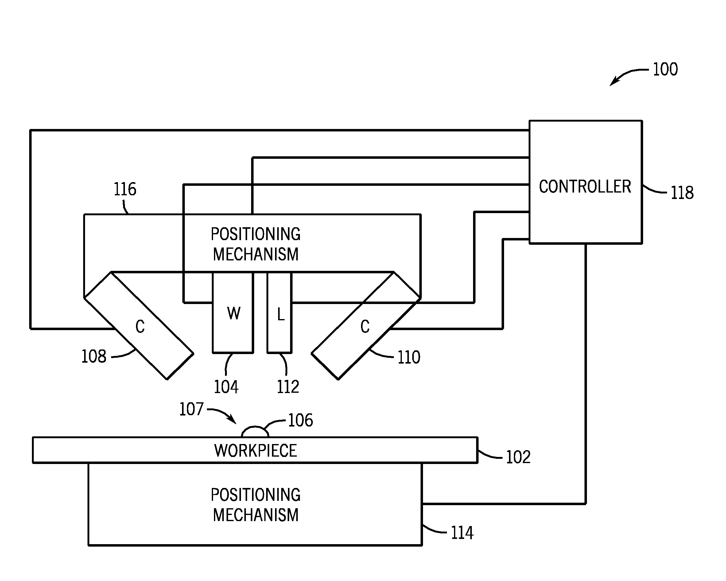
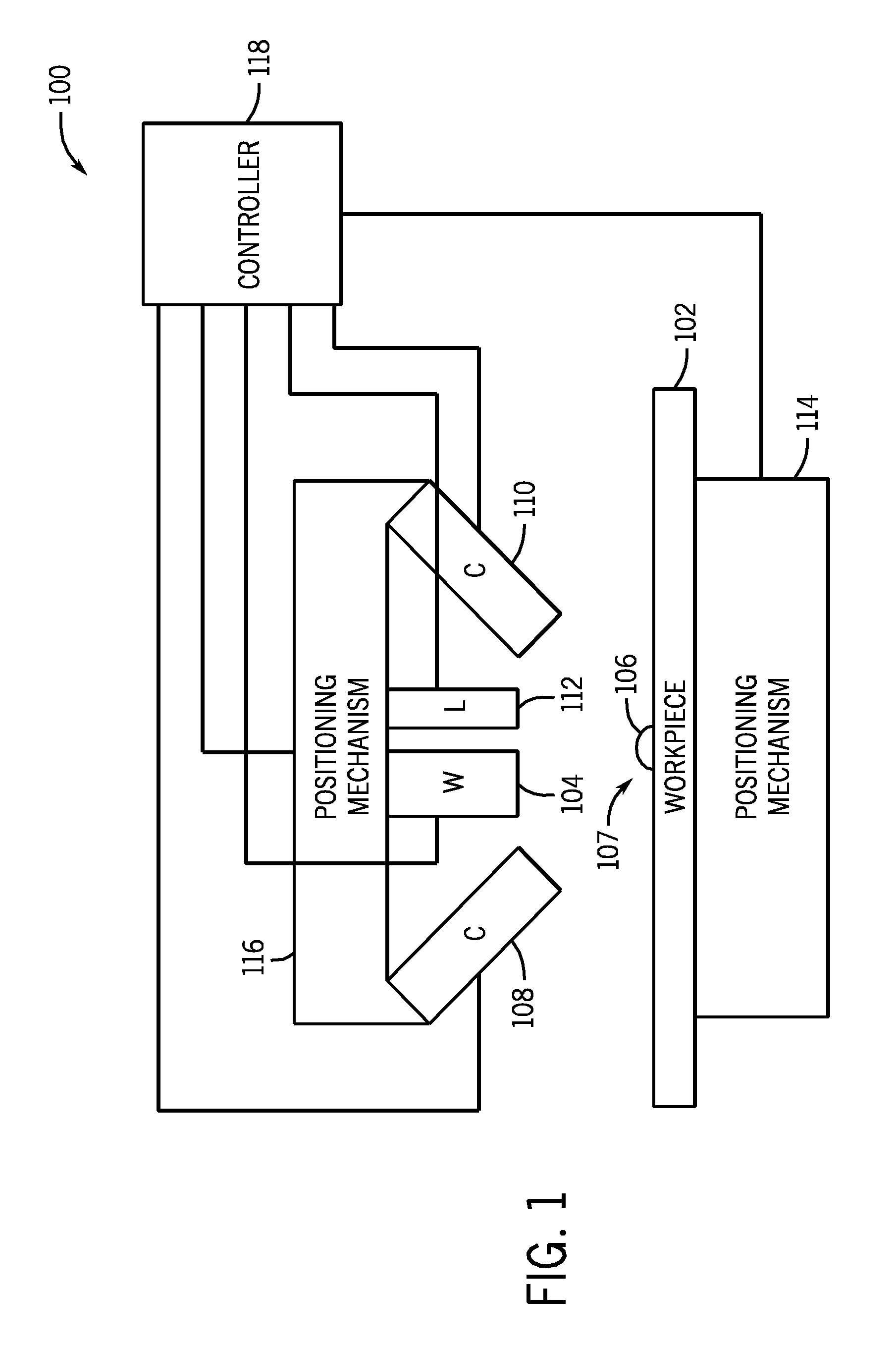
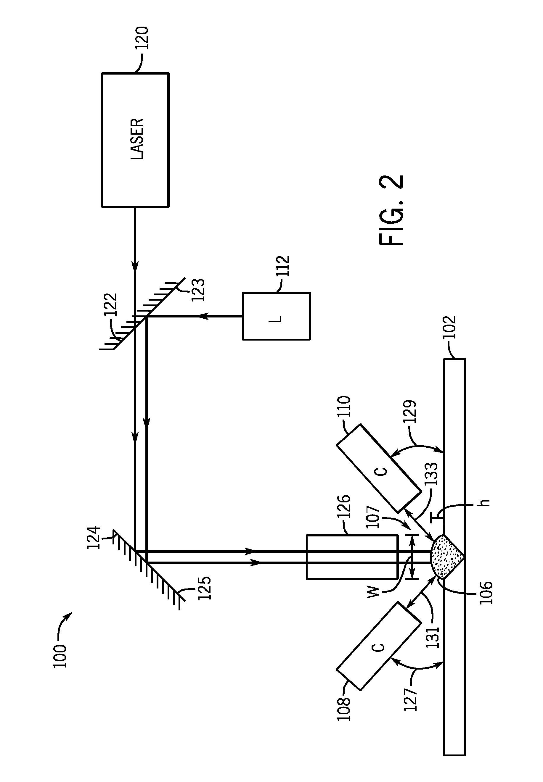
BACKGROUND OF THE INVENTION[0001]The subject matter disclosed herein relates to a welding control system and, more specifically, to a system for adjusting welding parameters based on stereoscopic bead visualization.[0002]Defects may develop during automated welding operations due to improper welder settings. For example, an output power of a welder, a feed rate of material into the welding zone and / or a speed of the welder relative to a workpiece may not be properly configured for a particular welding operation. These improper settings may result in unsatisfactory weld beads. For example, the weld bead may not have a proper height, width and / or penetration depth into the workpiece. Furthermore, the welder may wear away workpiece material surrounding the welding zone, a condition known as undercut. Such defects may degrade weld quality, thereby resulting in a weaker joint. Moreover, additional time-consuming and expensive finishing operations may be performed to correct the defects. ...

Claims


Application Information

Patent Timeline
Patent Type & Authority Applications(United States)
IPC IPC(8): B23K9/04
CPCB23K9/0956B23K9/32B23K15/0026B23K26/038B23K26/03B23K26/032B23K20/123B23K26/0344
Inventor CALLA, EKLAVYAMAITY, SANDIPRAPOL, UMAKANT DAMODARSILVIA, ALAN JOSEPH
Owner GENERAL ELECTRIC CO
Why Eureka
Try Eureka