
Portable binder with a rotating frame

a technology of rotating frame and binder, which is applied in the directions of liquid handling, transportation and packaging, and closure using stoppers, etc. it can solve the problem of not being able to adjust the visual angle of the electronic devices installed into the case structure for better operation by users, and achieve convenient use for users when they are, and facilitate the use of electronic devices. , the effect of dissipating heat from the covered parts

Inactive Publication Date: 2010-12-30
YANG SHANG WEN
View PDF14 Cites 61 Cited by
  • Summary
  • Abstract
  • Description
  • Claims
  • Application Information

AI Technical Summary

Benefits of technology

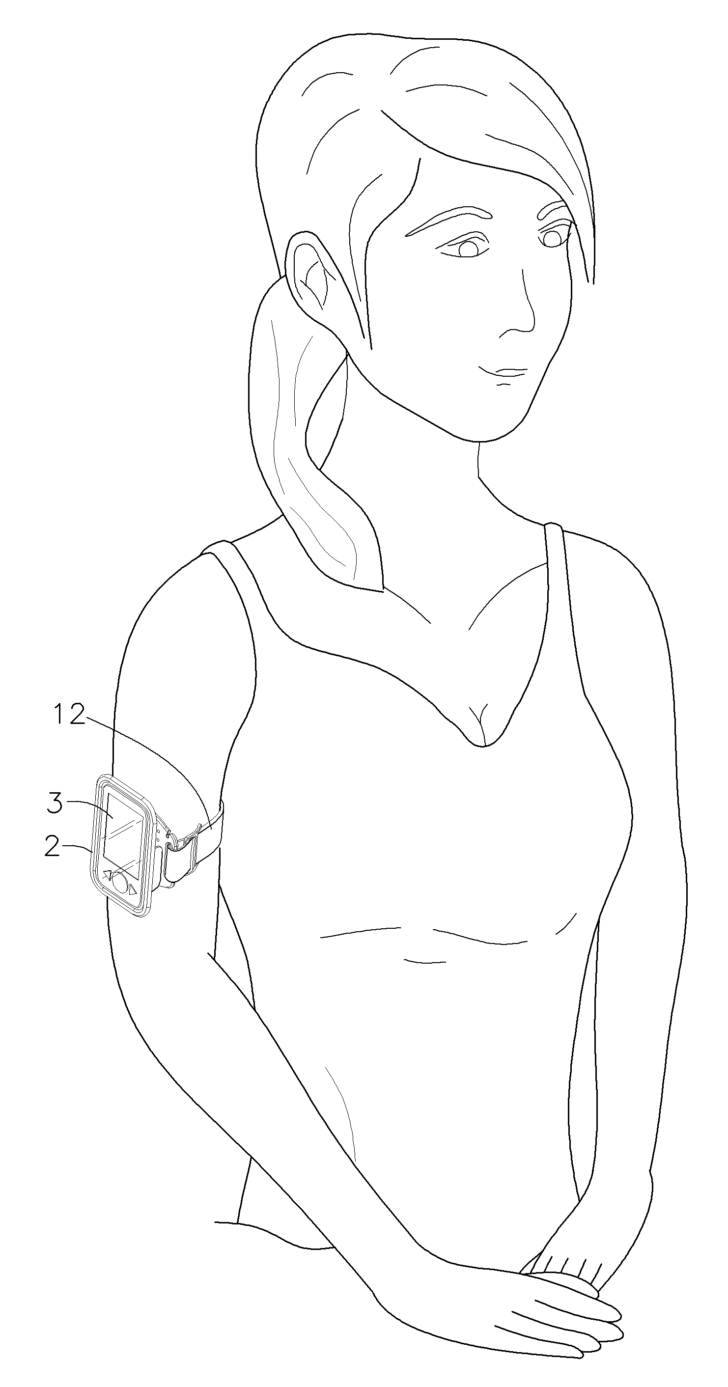
"The present invention provides a pedestal with a binding tape tightened around arms and a base, on which there is a shaft hole established to connect a coaxial connection shaft. A supporting plate is put in place to match the coaxial connection shaft, and a rotation shaft over an axial part is connected with the coaxial connection shaft for fixing. This allows for convenient use of the electronic device when placed onto a rotating frame. The invention also includes a mechanism for adjusting the visual angle by using the rotating frame. Additionally, the invention provides a solution for winding up and fixing a connection line of the electronic device by collecting and winding up the connection line around a round projecting plate at the bottom of the axial part of the body. The invention also includes an attaching cloth that can be attached to users' arms to dissipate heat and prevent eczema. Finally, the invention achieves the effect of tightly fastening the electronic device and preventing it from shedding by using the structure of the supporting plate of the body that surrounds the electronic device."

Problems solved by technology

However, these case structures are only suitable for attachment to users' waists and cannot rotate themselves, making it impossible to adjust the visual angle of the electronic devices installed into these case structures for better operation by users.

Method used


Image

  • Portable binder with a rotating frame
  • Portable binder with a rotating frame
  • Portable binder with a rotating frame

Examples


Embodiment Construction

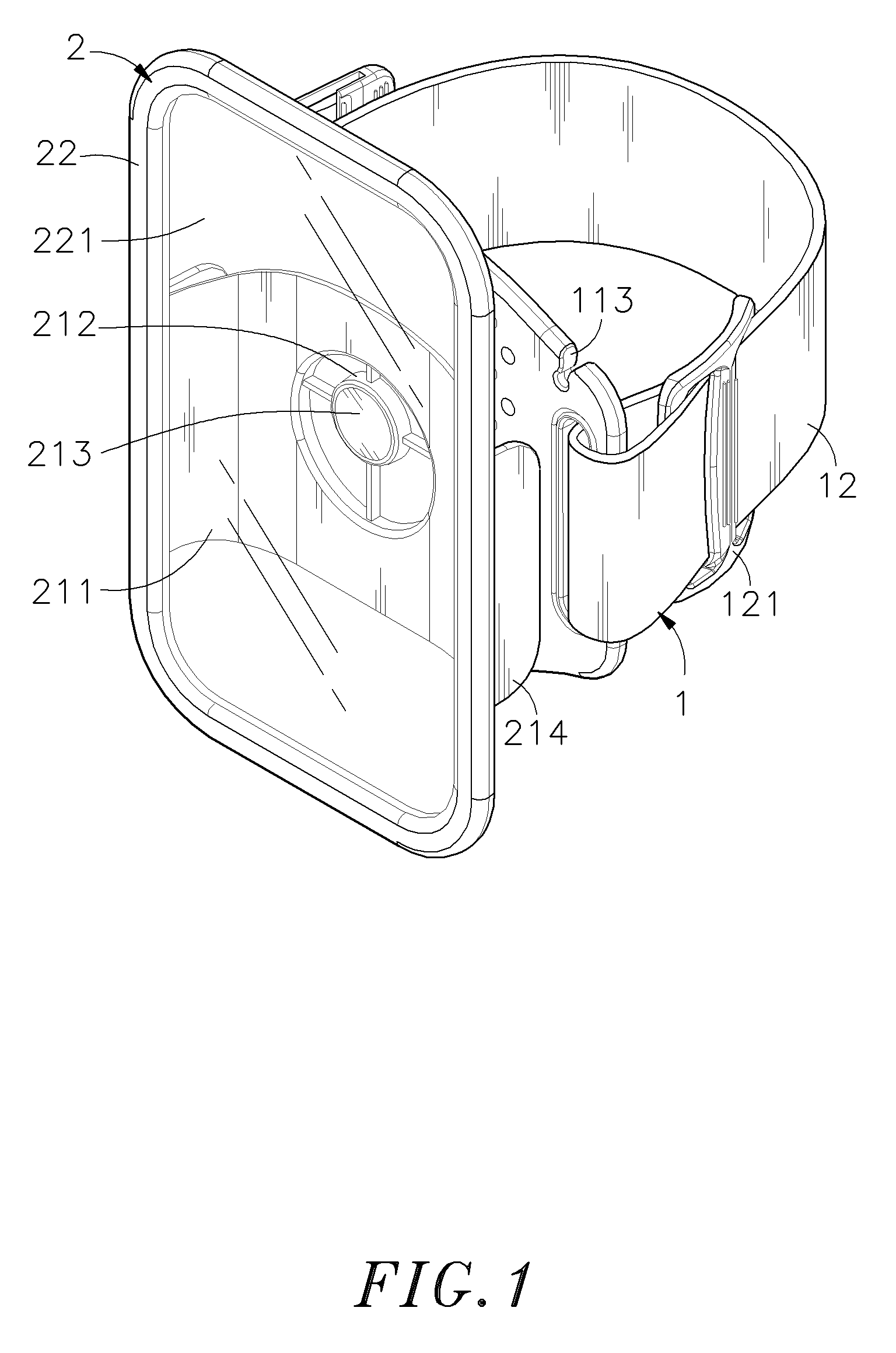
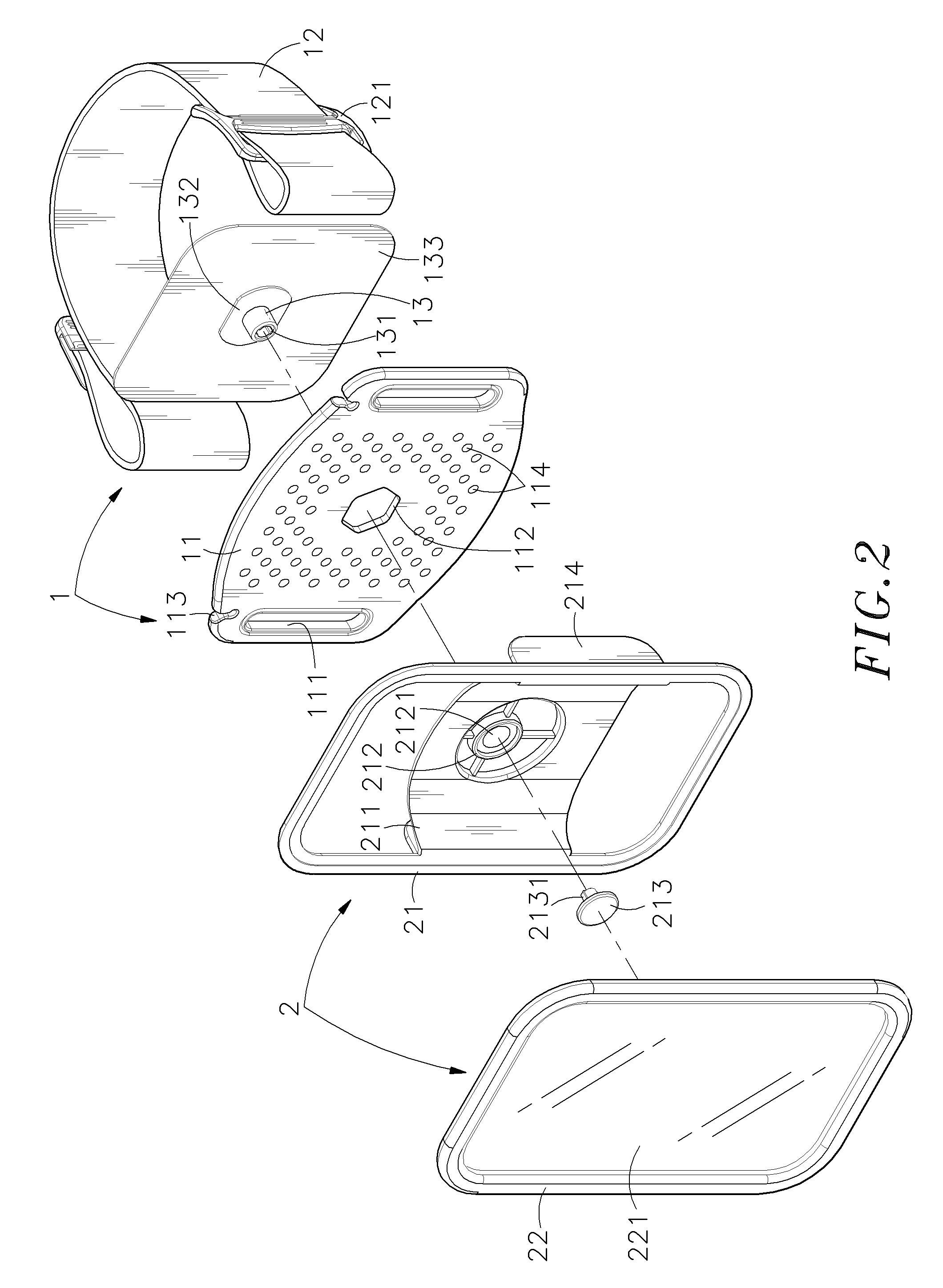
[0016]Refer to FIGS. 1˜3, which are a three-dimensional appearance drawing and two three-dimensional decomposition drawings from different angles of view according to one embodiment of the present invention. As shown clearly in these figures, the portable binder with a rotating frame disclosed in the present invention comprises a pedestal 1 and a rotating frame 2 (major components in the present invention and their characteristics will be described in detailed as follows), wherein:

[0017]The pedestal 1 contains a base 11 and on both sides of the base 11, there is a lacing hole 111 to be reeved by a binding tape 12, which includes an adjusting belt 121 for loosening or tightening the binding tape 12, and an axle hole 112 penetrates through the base 11 to combine a coaxial connection shaft 13.

[0018]The rotating frame 2 includes a body 21, and a supporting plate 211 is established and integrated below its surface on both sides. There is an axial part 212 that interconnects the coaxial c...


PUM


Abstract

The present invention relates to a portable binder with a rotating frame, comprising a pedestal and a rotating frame, wherein the pedestal has a base and on both sides of the base, there is a lacing hole to be reeved by a binding tape, which can be used by tightening it around arms. An axle hole penetrates through the base to combine a coaxial connection shaft, and on the base, a supporting plate is established concavely on both sides to cover a proposed electronic device, while an axial part is established to interconnect the coaxial connection shaft on the supporting plate, and on the axial part, there is a rotation shaft that can be coaxially connected with the coaxial connection shaft. When the binding tape reeving the base is fastened around users' arms, the body of the rotating frame can be utilized to fix the electronic device, thus achieving the effect of making the electronic device portable when users go out. Besides, the design of adjusting the visual angle by using the rotating frame makes it convenient to use the portable binder disclosed in the present invention.

Description

BACKGROUND OF THE INVENTION[0001]1. Field of the Invention[0002]The present invention relates to a portable binder with a rotating frame, particularly to the portable binder which has a binding tape tied around arms. Structurally, it is designed to include a rotator and a rotating frame for integrating electronic devices for users' convenience.[0003]2. Description of the Prior Art[0004]With progress in science and technology, different kinds of electronic devices, such as mobile phones, PDAs and MP3, have been developed one after another, leading to a very common phenomenon that everyone possesses a mobile phone or PDA in modern society.[0005]Usually, electronic devices are attached to users' waists by using case structures, which are fastened onto belts with a clamp on their surface. However, these case structures are only suitable for attachment to users' waists and cannot rotate themselves, making it impossible to adjust the visual angle of the electronic devices installed into t...

Claims


Application Information

Patent Timeline
Patent Type & Authority Applications(United States)
IPC IPC(8): A45C11/00A45C13/00
CPCA45F5/00A45F2005/008A45F2200/0516A45F2005/026A45F2005/025
Inventor YANG, SHANG-WEN
Owner YANG SHANG WEN
Learn More