Solid-state image device
a solid-state image and image technology, applied in the field of solid-state image devices, can solve the problem of not being able to meet the need for higher color reproducibility, and achieve the effect of improving the color reproducibility of primary color filters and suppressing the increase in spectral characteristics
- Summary
- Abstract
- Description
- Claims
- Application Information
AI Technical Summary
Benefits of technology
Problems solved by technology
Method used
Image
Examples
first embodiment
[0074]A solid-state image device according to a first embodiment of the present invention will be described below in accordance with the accompanying drawings.
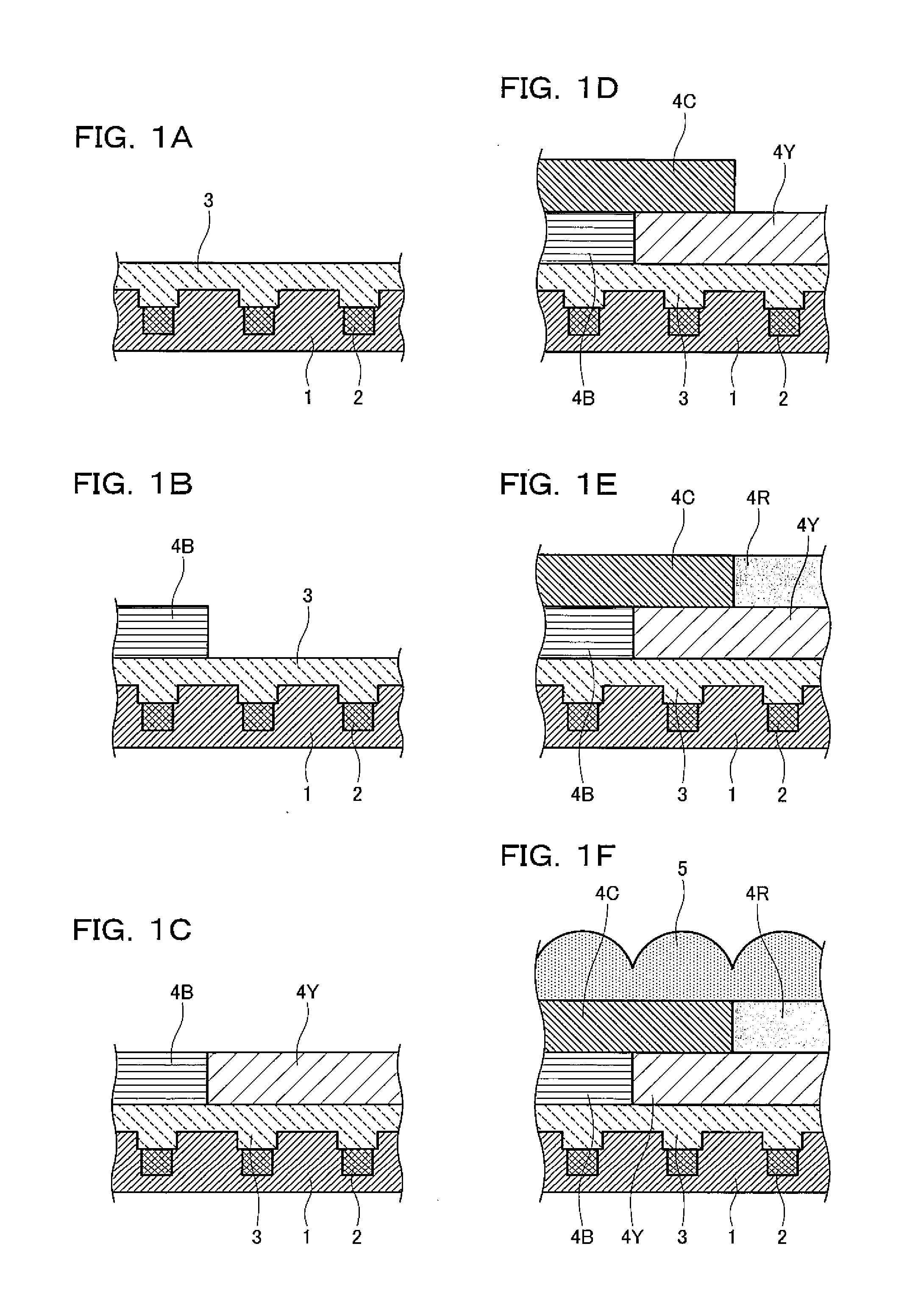
[0075]FIGS. 1A, 1B, 1C, 1D, 1E, and 1F are process sectional views showing a method of manufacturing the solid-state image device according to the first embodiment.
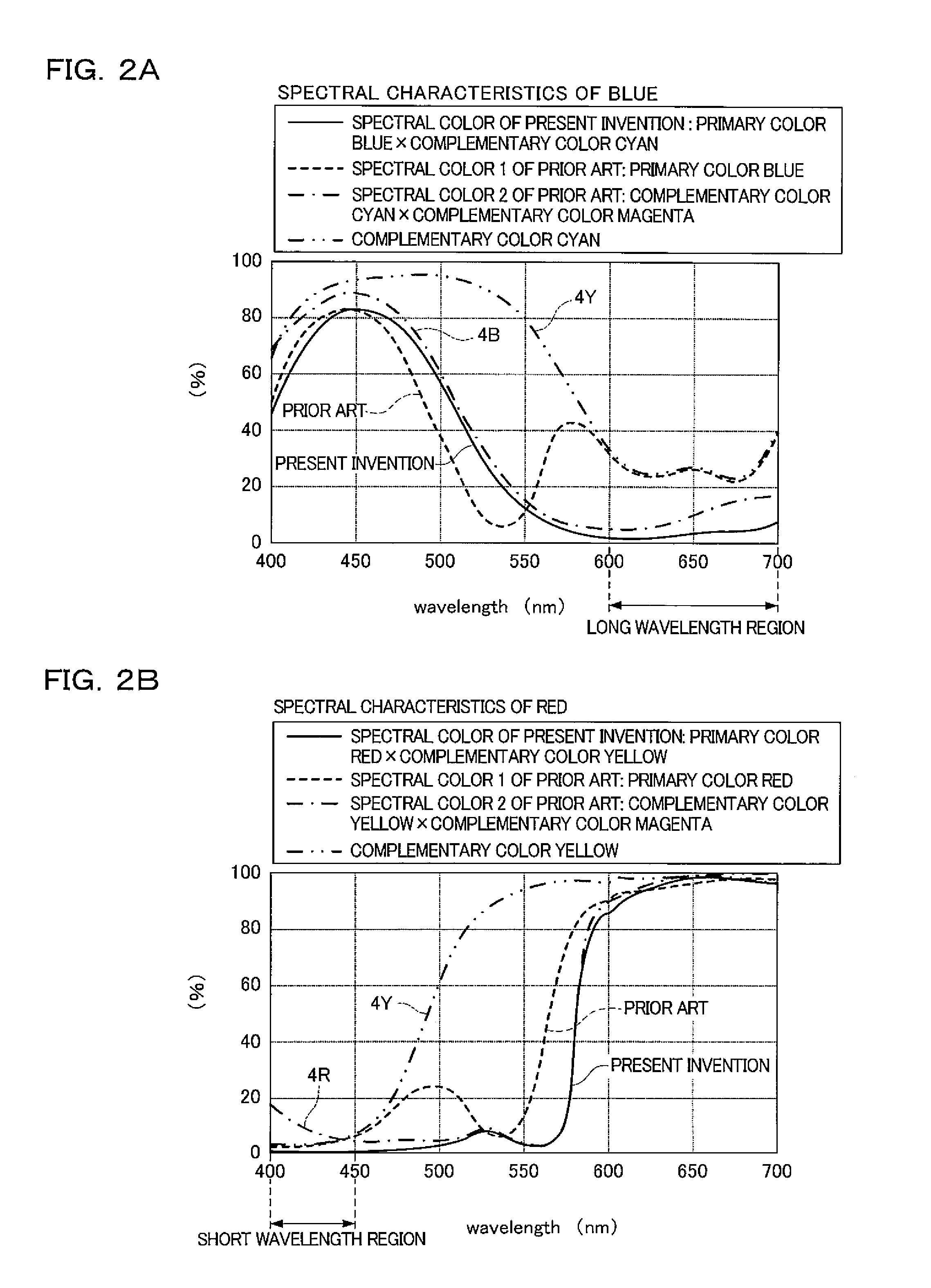
[0076]FIGS. 2A and 2B show the spectral characteristics of the solid-state image device according to the first embodiment. FIG. 2A shows the spectral characteristics of blue and FIG. 2B shows the spectral characteristics of red.
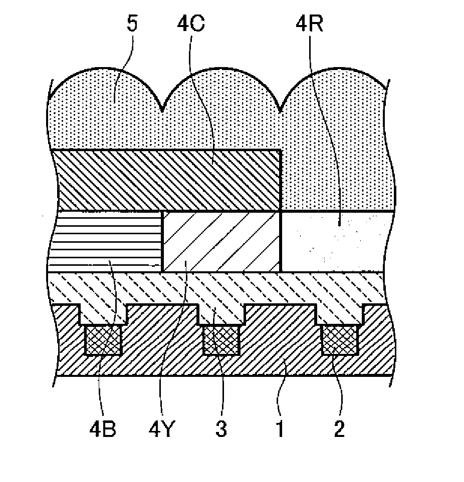
[0077]As shown in FIG. 1F, the solid-state image device is made up of a solid-state image element substrate 1; a plurality of light receiving portions 2 that are photodiodes formed in the solid-state image element substrate 1; an acrylic flat film 3 formed on the light receiving portions 2; a blue filter 4B and a yellow filter 4Y that are formed on the acrylic flat film 3; a cyan filter 4C formed on the blue filter 4B and the yellow filter 4Y...
second embodiment
[0090]FIGS. 3A, 3B, 3C, 3D, 3E, and 3F are process sectional views showing a method of manufacturing a solid-state image device according to a second embodiment.
[0091]As shown in FIG. 3F, the solid-state image device is made up of a solid-state image element substrate 1; a plurality of light receiving portions 2 that are photodiodes formed in the solid-state image element substrate 1; an acrylic flat film 3 formed on the light receiving portions 2; a blue filter 4B and a yellow filter 4Y that are formed on the acrylic flat film 3; a cyan filter 4C formed on the yellow filter 4Y; a red filter 4R formed on the yellow filter 4Y; and a plurality of microlenses 5 that are placed above the respective light receiving portions 2 and condense incident light onto the light receiving portions 2 placed below the respective microlenses 5. In the solid-state image device, it is necessary to reproduce primary colors that are red, green, and blue. The blue filter 4B is formed alone to reproduce blu...
third embodiment
[0103]FIGS. 4A, 4B, 4C, 4D, 4E, 4F, and 4G are process sectional views showing a method of manufacturing a solid-state image device according to a third embodiment.
[0104]As shown in FIG. 4G, the solid-state image device is made up of a solid-state image element substrate 1; a plurality of light receiving portions 2 that are photodiodes formed in the solid-state image element substrate 1; an acrylic flat film 3 formed on the light receiving portions 2; a blue filter 4B, a green filter 4G, and a red filter 4R that are formed on the acrylic flat film 3; a cyan filter 4C formed on the blue filter 4B; a yellow filter 4Y formed on the red filter 4R; and a plurality of microlenses 5 that are placed above the respective light receiving portions 2 and condense incident light onto the light receiving portions 2 placed below the respective microlenses 5. In the solid-state image device, it is necessary to reproduce primary colors that are red, green, and blue. The cyan filter 4C is stacked on ...
PUM
 Abstract
Description
Claims
Application Information
 - R&D
- Intellectual Property
- Life Sciences
- Materials
- Tech Scout
- Unparalleled Data Quality
- Higher Quality Content
- 60% Fewer Hallucinations
Browse by: Latest US Patents, China's latest patents, Technical Efficacy Thesaurus, Application Domain, Technology Topic, Popular Technical Reports.
© 2025 PatSnap. All rights reserved.Legal|Privacy policy|Modern Slavery Act Transparency Statement|Sitemap|About US| Contact US: help@patsnap.com


