Method of processing dummy pattern based on boundary length and density of wiring pattern, semiconductor design apparatus and semiconductor device
a technology of boundary length and density, which is applied in the direction of computer aided design, program control, instruments, etc., can solve the problems of changing the etching rate, reducing the effect of sidewall protective film, and breaking of wires, so as to curb the variation of wiring patterns formed and the effect of curbing the variation of wiring patterns
- Summary
- Abstract
- Description
- Claims
- Application Information
AI Technical Summary
Benefits of technology
Problems solved by technology
Method used
Image
Examples
first embodiment
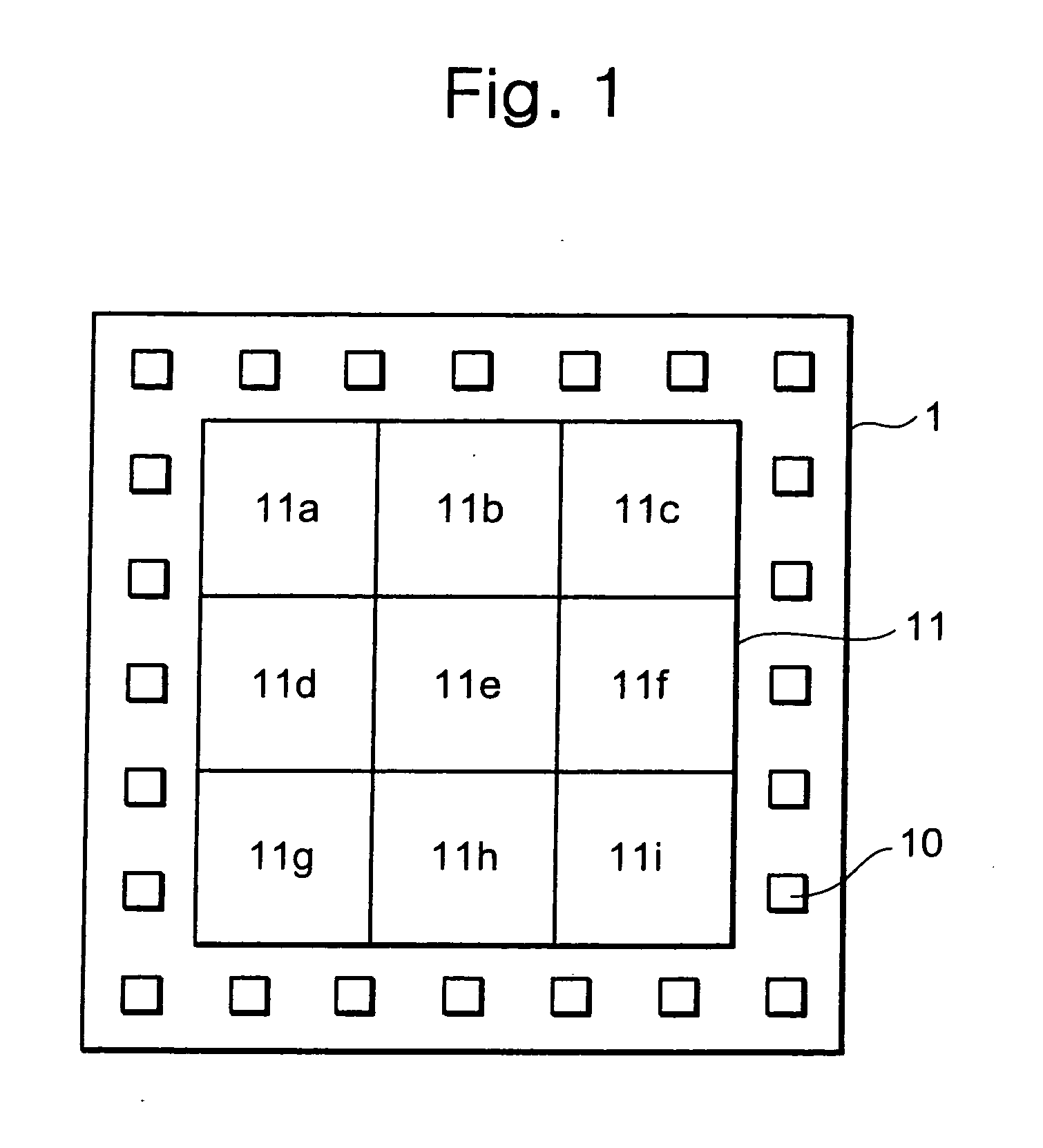
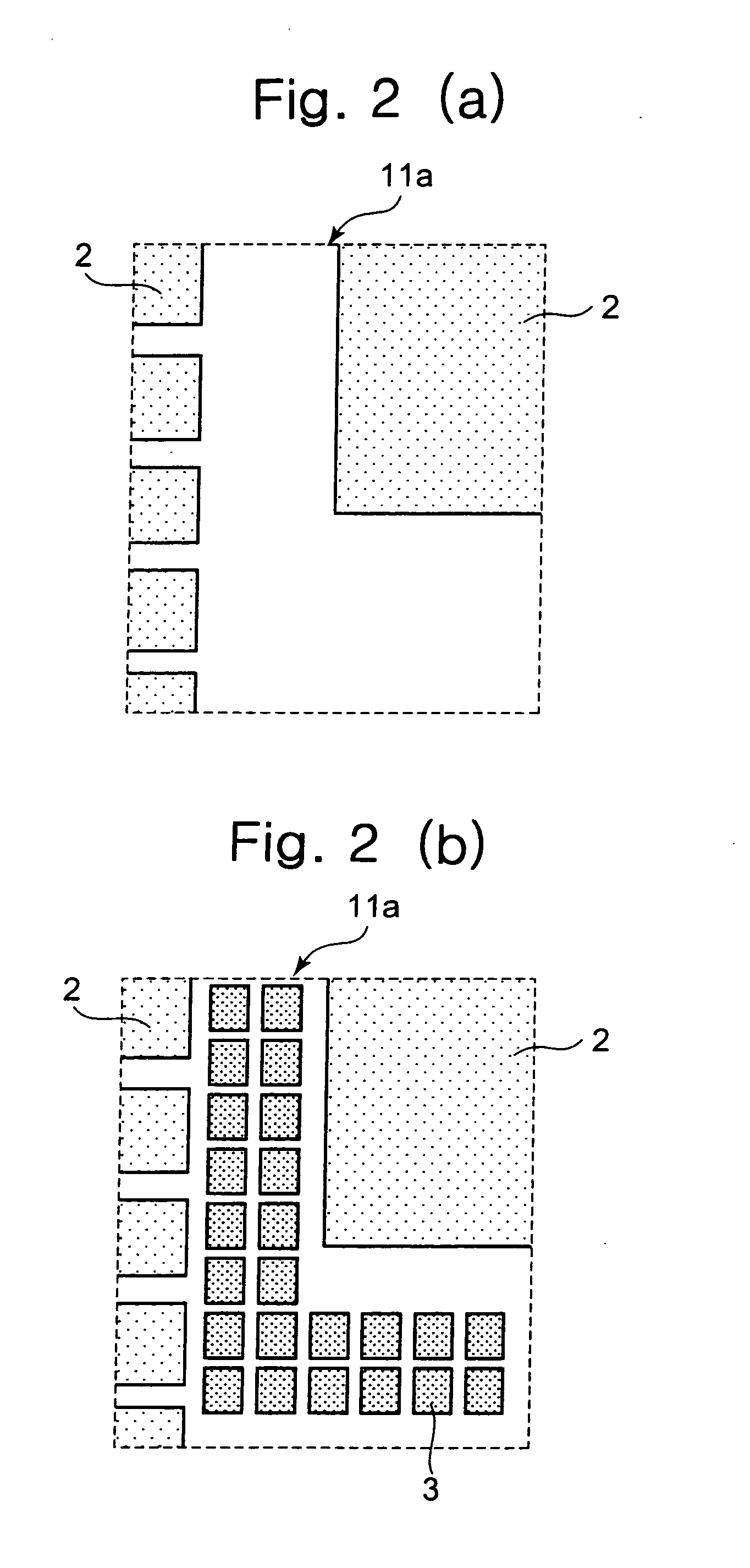
[0029]FIG. 1 shows a diagrammatic view of a semiconductor device 1 according to a first embodiment. As shown in FIG. 1, the semiconductor device 1 includes pads 10 being input / output terminals of the semiconductor device 1 and a wiring region 11 where wiring patterns of the semiconductor device 1 are formed. The wiring region 11 is divided into a plurality of divided regions 11a to 11i. The divided regions 11a to 11i are set such that each region has the same area, for example. Taking the divided regions 11a to 11d as examples out of the divided regions 11a to 11i, detailed descriptions will be given of the relation between wiring patterns and dummy patterns in a divided region. Please note that wiring patterns and dummy patterns are patterns which are formed of the same material on a semiconductor device, and are made of a metal material such as aluminum or copper.
[0030]Descriptions will be given of the divided region 11a. FIG. 2 (a) shows a diagrammatic view of layout before placi...
second embodiment
[0064]In the first embodiment, the shape of a dummy cell to be added is changed based on the density of the wiring patterns and the total value of the length of the peripheries of the wiring patterns. In contrast, a method of placing dummy patterns according to a second embodiment is to place a dummy cell in accordance with the density of the wiring patterns, and subsequently divide the placed dummy cell in accordance with the total value of the length of the peripheries of the wiring patterns in order to confine the total value of the length of the peripheries within a specified range.
[0065]FIG. 13 shows a flow chart of the method of placing dummy patterns. Please note that the descriptions will be omitted for a case where the density of the wiring patterns is within the specified range and there is no need to add dummy cells. In the flow of placing dummy patterns according to the second embodiment, data collected after laying wiring patterns out, when the placement of wiring patte...
PUM
 Abstract
Description
Claims
Application Information
 - R&D
- Intellectual Property
- Life Sciences
- Materials
- Tech Scout
- Unparalleled Data Quality
- Higher Quality Content
- 60% Fewer Hallucinations
Browse by: Latest US Patents, China's latest patents, Technical Efficacy Thesaurus, Application Domain, Technology Topic, Popular Technical Reports.
© 2025 PatSnap. All rights reserved.Legal|Privacy policy|Modern Slavery Act Transparency Statement|Sitemap|About US| Contact US: help@patsnap.com


