Electronic thermometer

a thermometer and electronic technology, applied in the field of electronic thermometers, can solve the problems of affecting the human body, affecting the body, and difficult to employ anti-static measures, and achieve the effect of preventing breakage of internal parts

Active Publication Date: 2010-12-30
OMRON HEALTHCARE CO LTD
View PDF13 Cites 17 Cited by
  • Summary
  • Abstract
  • Description
  • Claims
  • Application Information

AI Technical Summary

Benefits of technology

[0035]As described above, the invention can provide a simple structure that determines a state of contact with a human body without directly exerting an electric influence on a human body while preventing breakage of internal parts due to static electricity.

Problems solved by technology

However, in the method that senses a contact state by determining whether a measurement target portion has pushed a switch or not, when a probe is in a contact position, or in a method that senses a contact state depending on a contact that occurs between two contact points owing to deformation of the probe caused by a pushing force of the measurement target portion; a detection error may occur due to the contact with or pushing by a portion other than the human body or by a portion other than the measurement target portion.
In these methods, since a metal portion exposed on the surface of the probe comes into contact with a human body, electricity directly flows through the human body so that current leakage of the like may adversely affect the human body.
Also, it is difficult to employ antistatic measures because the electrode is arranged on the probe surface, and the static electricity may break internal parts such as a CPU.
In a structure that has a protruding switch or an electrode near the probe, a user may feel uncomfortable when the switch or electrode touches the human body.

Method used


Image

  • Electronic thermometer
  • Electronic thermometer
  • Electronic thermometer

Examples


first embodiment

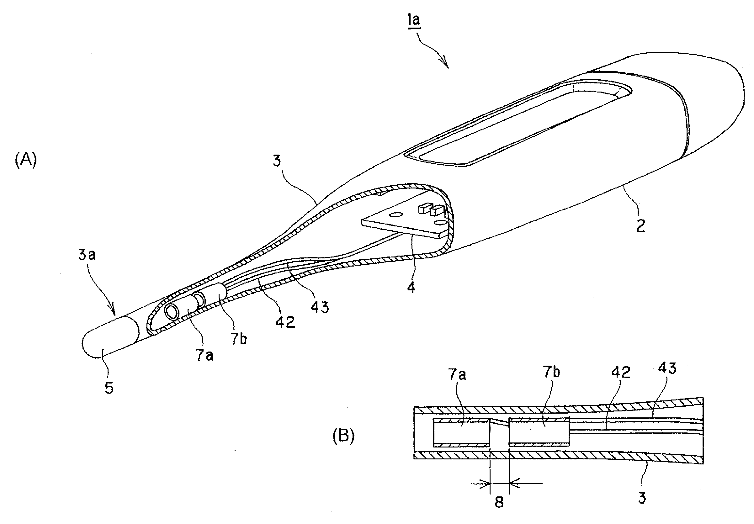
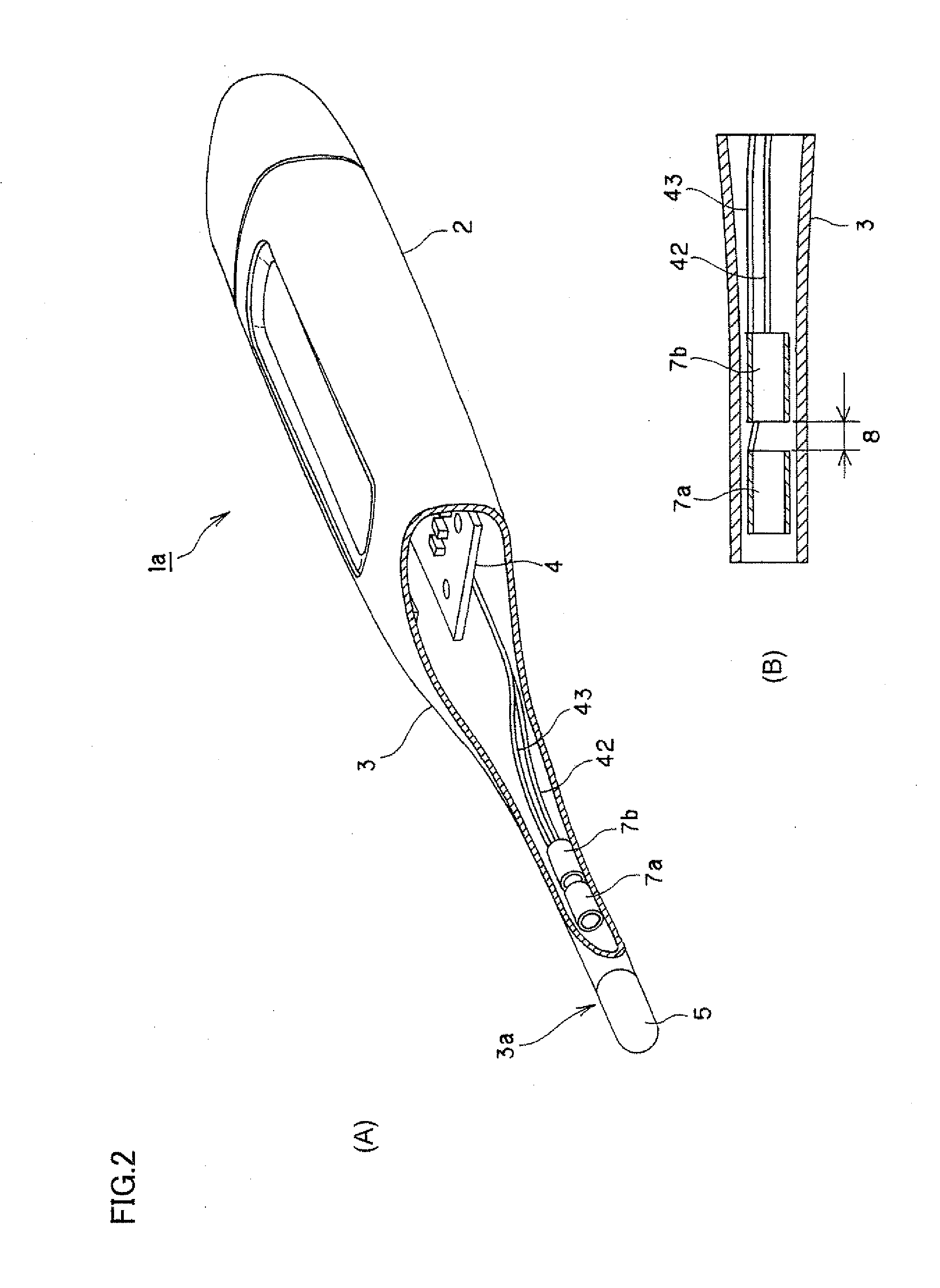
[0063]Referring to FIGS. 2A to 6, an electronic thermometer according to a 1st-a embodiment of the invention will be described below. FIGS. 2A and 2B are schematic views showing a distinctive portion of the electronic thermometer according to this embodiment. FIG. 2A is a perspective view with a probe partially cut way, and FIG. 2B is a longitudinal section of a tip-side portion of the probe. FIG. 3 is a graph showing a change that occurs in electrostatic capacity when temperature measuring unit 3a is in appropriate contact with the measurement target portion. In this graph, the abscissa gives a time (s) and the ordinate gives an electrostatic capacity (pF). FIG. 4 is a schematic block diagram showing an electrical structure of the electronic thermometer. FIGS. 5A and 5B illustrate a principle of change that occurs in electrostatic capacity between electrodes in response to contact with a human body. FIG. 5A illustrates the state of electric charges that are present between the elec...

second embodiment

[0093]Referring to FIGS. 11A and 11B, an electronic thermometer 1b according to a second embodiment of the invention will be described below. FIGS. 11A and 11B are schematic views showing a distinctive portion of electronic thermometer 1b according to this embodiment. FIG. 11A is a perspective view showing a probe with a certain part cut away, and FIG. 11B is a longitudinal section of the probe. The following description will be given on only differences from the foregoing embodiment. The same members and structures bear the same reference numbers, and description thereof is not repeated. The same members and structures perform or offer substantially the same operations, effects and the like.

[0094]This embodiment uses a pair of spiral conductors 7c and 7d as human body contact sensor 7.

[0095]As shown in FIGS. 11A and 11B, the spirals of conductors 7c and 7d are coaxial with each other, and are turned in the same direction. Also, conductors 7a and 7b arranged in the hollow of probe 3...

third embodiment

[0098]Referring to FIGS. 12A and 12B, description will be given on an electronic thermometer 1c according to a third embodiment of the invention. FIGS. 12A and 12B are schematic views showing a distinctive portion of electronic thermometer 1c according to a third embodiment. FIG. 12A is a perspective view showing a probe with a certain part cut away, and FIG. 12B is a longitudinal section of the probe. The following description will be given on only differences from the foregoing embodiments. The same members and structures bear the same reference numbers, and description thereof is not repeated. The same members and structures perform or offer substantially the same operations, effects and the like.

[0099]As human body contact sensor 7, this embodiment uses a pair of conductors 7e and 7f each having a semicylindrical form.

[0100]As shown in FIGS. 12A and 12B, conductors 7e and 7f have forms that can be prepared by longitudinally dividing a cylinder extending in the longitudinal direc...


PUM

PropertyMeasurementUnit
temperatureaaaaaaaaaa
body temperatureaaaaaaaaaa
contact resistanceaaaaaaaaaa

Abstract

An electronic thermometer includes a hollow probe provided at its longitudinal tip with a temperature measuring unit having a temperature sensor for sensing a temperature, electrodes neighboring to the temperature sensor and arranged in the hollow of the probe, and a determining unit for determining whether temperature measuring unit is in appropriate contact with a measurement target portion of a user or not, based on a change in electrostatic capacity sensed using the electrodes.

Description

TECHNICAL FIELD[0001]The present invention relates to an electronic thermometer.BACKGROUND ART[0002]Such an electronic thermometer has been known that can correctly measure a body temperature by determining whether a human body is in contact with a temperature sensor or not.[0003]As such a kind of electronic thermometer, for example, a patent document 1 has disclosed an electronic thermometer that utilizes, for sensing a contact with a human body, a switch, a contact resistance, an electrostatic capacity, a humidity, a pressure (contact), a temperature comparison, a change in temperature and the like.[0004]However, in the method that senses a contact state by determining whether a measurement target portion has pushed a switch or not, when a probe is in a contact position, or in a method that senses a contact state depending on a contact that occurs between two contact points owing to deformation of the probe caused by a pushing force of the measurement target portion; a detection e...

Claims


Application Information

Patent Timeline
Patent Type & Authority Applications(United States)
IPC IPC(8): G08B21/00G01K7/00
CPCG01K13/002G01K1/146G01K13/20
Inventor HIRAMATSU, HIROSHIFUJITA, YASUONAKANISHI, YOSHIHITOONISHI, YOSHIHIDEISHIHARA, DAISUKEFUKUI, ATSUKOTOMIOKA, MASAKIMORITA, KATSUYOSHI
Owner OMRON HEALTHCARE CO LTD
Why Eureka
Try Eureka