Multiband Antenna

a multi-band antenna and antenna technology, applied in the field of antennas, can solve the problems of only being suitable for wlan operation, difficult to be embedded inside a mobile communication device, and bringing engineers challenges, and achieve the effect of reducing the size of the antenna

Active Publication Date: 2010-12-30
ACER INC
View PDF4 Cites 46 Cited by
  • Summary
  • Abstract
  • Description
  • Claims
  • Application Information

AI Technical Summary

Benefits of technology

[0007]It is an object of the present invention to provide a multiband antenna which can generate two wide operating bands in covering multiband WWAN operation and occupy a reduced antenna size.

Problems solved by technology

The WLAN antennas used in prior-art laptop computers are mostly inverted-F antennas, which bring challenges to engineers because of their sizes when they are applied for WWAN operation.
However, the antenna is only suitable for WLAN operation.
When the antenna is applied for multiband WWAN operation, it is difficult to be embedded inside a mobile communication device because the antenna will have a large size.

Method used


Image

  • Multiband Antenna
  • Multiband Antenna
  • Multiband Antenna

Examples


first embodiment

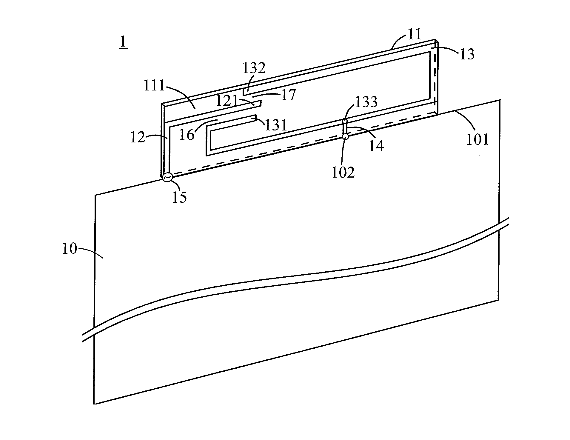
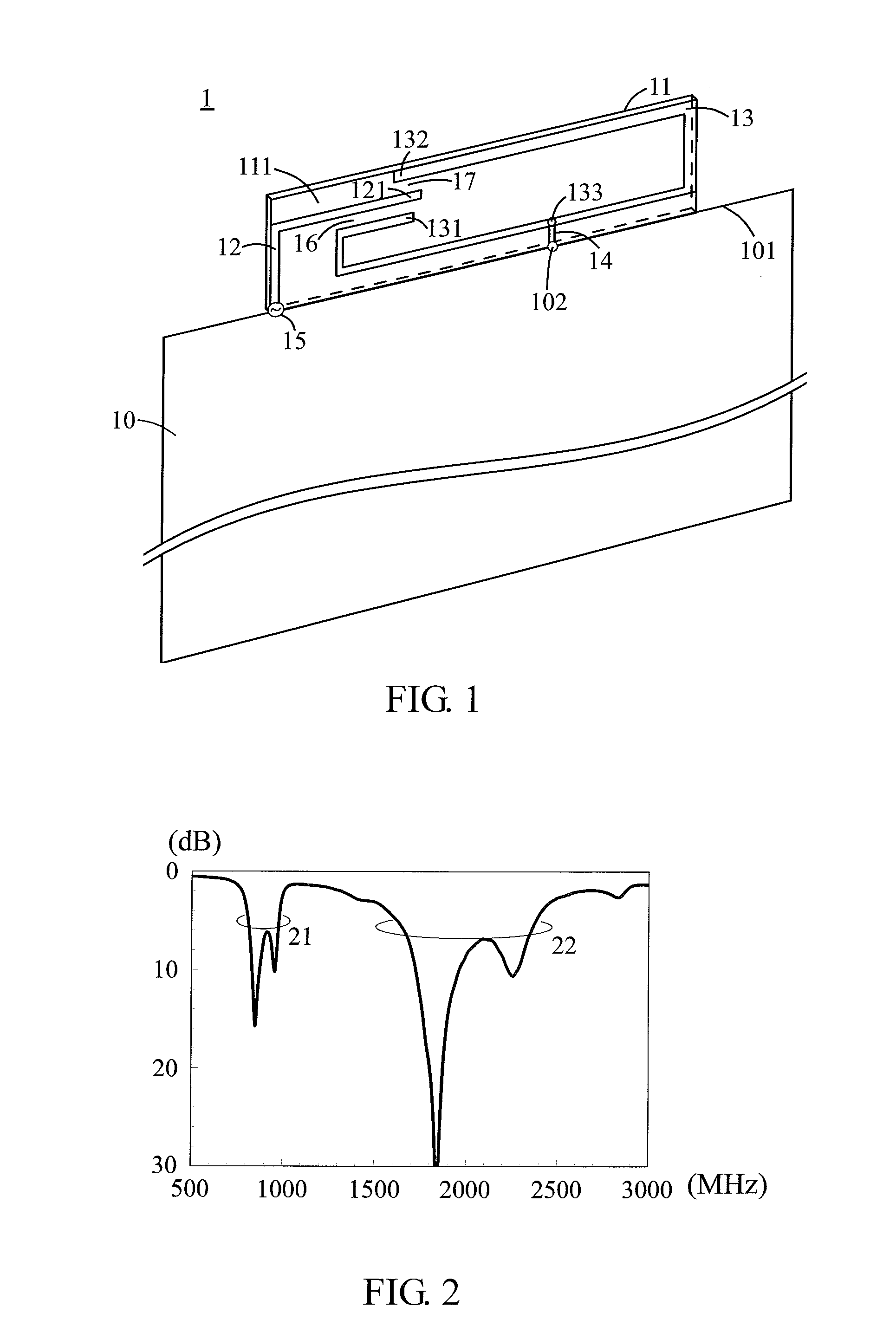
[0026]FIG. 2 illustrates a diagram of a measured return loss of the multiband antenna in the present invention. In this embodiment, in order to simulate the supporting metal frame of the LCD panel of laptop computer, the ground plane 10 is chosen to be 260 mm long and 200 mm wide; the radiating metal portion is formed by printing or etching on the dielectric substrate 11 which is 65 mm long, 10 mm wide and 0.8 mm thick.

[0027]The signal source 15 feeds the energy to the first metal portion 12, which is then coupled from the first metal portion 12 to the second metal portion 13 via the first coupling gap 16 (which has a width of less than 2 mm), wherein the first metal portion 12, the second metal portion 13 and the first coupling gap 16 form a loop-like path to the shorting metal line 14. Similarly, the energy can be coupled to the second metal portion 13 via the second coupling gap 17 (which has a width of less than 2 mm), wherein the first metal portion 12, the second metal portion...
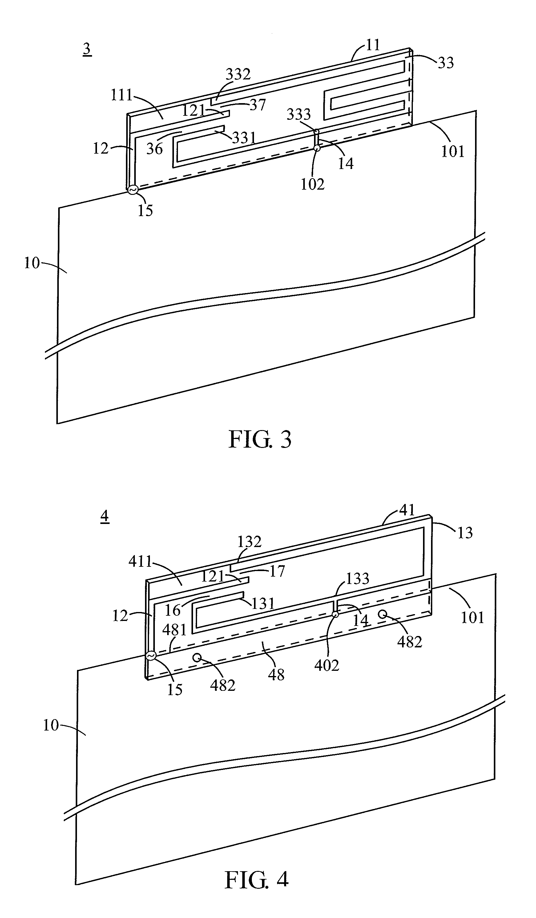
third embodiment

[0029]Please refer to FIG. 4 for a structural view of a multiband antenna 4 in the present invention. The multiband antenna 4 comprises: the ground plane 10, the dielectric substrate 41 and the radiating metal portion. For example, the ground plane 10 can be a supporting metal frame of a LCD panel of a laptop computer. The dielectric substrate 41 is located at the side edge 101 of the ground plane 10 (with a portion of the dielectric substrate 41 overlapping the side edge 101), the dielectric substrate 41 is approximately parallel to the ground plane 10 and extends outwardly.

[0030]In this embodiment, the radiating metal portion is formed on a surface 411 of the dielectric substrate 41 by printing or etching. The radiating metal portion comprises an antenna ground plane 48, the first metal portion 12 and the second metal portion 13. This embodiment is designed to meet different antenna implementations, wherein the radiating metal portion is first electrically connected to the antenna...


PUM


Abstract

The present invention discloses a multiband antenna. The antenna comprises a ground plane, a dielectric substrate and a radiating metal portion. The dielectric substrate is located at one side edge of the ground plane. The radiating metal portion is disposed on one surface of the dielectric substrate and comprises a first metal portion and a second metal portion. The first metal portion is substantially of an L-shape. One end of the first metal portion is adjacent to the side edge of the ground plane and is the antenna's feeding point connected to a signal source, and the other end of the first metal portion is an open end. The second metal portion comprises a U-shape portion. The second metal portion comprises a first open end and a second open end, which are respectively located on two opposite sides of the open end of the first metal portion. The first open end has a first coupling gap between the first open end and the open end of the first metal portion; and the second open end has a second coupling gap between the second open end and the open end of the first metal portion. The second metal portion is further short-circuited to the ground plane by a shorting metal line.

Description

BACKGROUND OF THE INVENTION[0001]1. Field of the Invention[0002]The present invention relates to an antenna, and more particularly, to a multiband antenna which is able to cover multiband operation in the mobile communication devices.[0003]2. Description of the Related Art[0004]Recently, various kinds of wireless communication applications emerge with the development and improvement of wireless communication technologies, such as the laptop computers combined with wireless communication capabilities. For the present most laptop computers are capable of wireless local area network (WLAN) operation; however, in order to provide more functionalities, the laptop computers should be equipped with antennas capable of multiband operation to cover the wireless wide area network (WWAN) operation as well.[0005]The WLAN antennas used in prior-art laptop computers are mostly inverted-F antennas, which bring challenges to engineers because of their sizes when they are applied for WWAN operation....

Claims


Application Information

Patent Timeline
Patent Type & Authority Applications(United States)
IPC IPC(8): H01Q1/48H01Q1/38H01Q5/10
CPCH01Q1/2266H01Q9/0421H01Q5/392H01Q5/20H01Q9/42
Inventor WONG, KIN-LULEE, LI-CHUN
Owner ACER INC
Why Eureka
Try Eureka